English
 Italiano
 Українська
 Русский
 Español

Parametric design and robotics connect editable digital geometry with programmable physical fabrication. Instead of modelling one final object and then determining separately how to manufacture it, designers can define relationships, variables and constraints that generate both the geometry and the information required to produce it.
The industrial robot becomes the physical execution layer of that system. It can mill, cut, deposit, place, form, scan or assemble material according to paths generated from the digital model.
However, the transition from parametric geometry to robotic movement is not automatic. A valid three-dimensional form is not necessarily reachable, collision-free, structurally stable or manufacturable. The workflow must connect design intent with tooling, robot kinematics, material behaviour, fixtures, calibration and process control.
Quick answer
- Parametric design defines geometry through relationships and editable variables.
- Process planning converts geometry into fabrication operations.
- Robot programming converts those operations into positions, orientations and motion commands.
- Simulation checks reach, collisions and robot configurations.
- Calibration connects the digital coordinate system to the real robot, tool and workpiece.
- Physical testing validates material behaviour and process quality.
The workflow succeeds when design data and fabrication constraints remain connected throughout the project.
What parametric design means in robotic fabrication
Parametric design defines a model through rules, dependencies and variables rather than through isolated fixed geometry.
A designer may control:
- dimensions and proportions;
- surface curvature;
- component spacing;
- pattern density;
- material thickness;
- orientation relative to structure or environment;
- the number and position of repeated elements;
- permitted ranges of geometric variation.
When one parameter changes, related parts of the model update according to the rules built into the system.
This is particularly useful in robotic fabrication because industrial robots are not limited to producing identical parts. A parametric model can generate a family of related components, with each component receiving a corresponding fabrication path.
The repeatable element is therefore the design and production logic. The individual physical outputs may remain different.
Why parametric geometry is not yet a robot program
A digital model describes shape. A robot program must describe executable movement.
The robot needs more information than a curve or surface:
- the position of the tool centre point;
- the orientation of the tool at every relevant location;
- movement type and direction;
- speed and acceleration;
- process states such as spindle, extrusion or gripper control;
- approach and departure paths;
- safe transitions between operations;
- workpiece and fixture coordinates;
- collision and joint-limit constraints.
A curve may look correct on screen while producing an impossible wrist orientation. A surface may be geometrically continuous but require the robot to pass through a fixture. A toolpath may remain inside the nominal working envelope while forcing the robot close to a singularity or joint limit.
The design model must therefore pass through a process-planning and robot-programming layer before it can be executed safely.
The complete parametric robotic fabrication workflow
| Workflow stage | Primary task | Main technical risk |
|---|---|---|
| Parametric modelling | Define geometry, relationships, variables and design constraints. | Generating forms that ignore fabrication or robot limitations. |
| Process definition | Choose how the material will be cut, deposited, formed, placed or assembled. | Selecting a process incompatible with the material or required quality. |
| Toolpath generation | Convert geometry into ordered process paths and tool orientations. | Poor access, excessive path length or invalid tool orientation. |
| Robot simulation | Evaluate reach, joint motion, collisions, singularities and external axes. | Assuming a visually valid path is physically executable. |
| Postprocessing | Translate generic path data into controller-specific robot code. | Incorrect syntax, motion commands, frames or process instructions. |
| Calibration | Align robot, tool, workpiece and digital coordinate systems. | Position and orientation errors in the physical process. |
| Physical validation | Test the real process, material response and output quality. | Material, tooling or dynamic behaviour differing from simulation. |
Key distinction: parametric modelling generates design information. A complete robotic fabrication workflow converts that information into a technically valid and physically tested process.
How Rhino and Grasshopper fit into the workflow
Rhino is commonly used for three-dimensional geometry, while Grasshopper provides a visual environment for building parametric relationships and generative logic.
Within Grasshopper, designers can create systems that:
- generate related geometric variants;
- divide surfaces into fabrication paths;
- calculate points, vectors and planes;
- orient tools relative to surfaces;
- sequence components or operations;
- evaluate geometric constraints;
- connect design parameters with process parameters;
- export data for simulation or robot programming.
The strength of this environment is that the design logic remains editable. Changing a component dimension, pattern density or surface condition can update the geometry and the downstream fabrication data.
But Grasshopper alone does not guarantee a reliable robot process. The definition must still account for the selected robot, controller, tool, material and cell layout.
How a robot path is generated from parametric geometry
A robot path is typically represented by a sequence of targets. Each target contains both a position and an orientation.
For a simple drawing process, the position may follow a curve while the tool remains perpendicular to a flat surface. For milling or deposition on a three-dimensional surface, the orientation may need to change continuously.
A path-generation workflow may include:
- selecting or generating the source geometry;
- dividing it into ordered points or curves;
- calculating local surface directions or normals;
- constructing a tool coordinate frame at each target;
- offsetting the path according to tool length or process distance;
- defining approach, operation and departure movements;
- assigning speed and process parameters;
- checking path continuity and orientation changes;
- sending the targets to a robot simulation environment.
The quality of the final operation depends heavily on how these targets are generated. Excessively dense points may produce very large programs or unstable motion. Too few points may create visible segmentation or reduce geometric fidelity.
Why tool orientation matters as much as position
Designers often concentrate on where the robot tool should be located. In many processes, how the tool is oriented is equally important.
Orientation affects:
- cutting direction and tool engagement;
- deposition angle and layer bonding;
- brush or applicator contact;
- gripper access to a component;
- camera perspective;
- collision risk;
- robot wrist configuration;
- cable and hose behaviour.
A parametric system can derive orientation from a surface normal, guide curve, target object or process-specific rule.
However, a mathematically consistent orientation field may still create abrupt wrist rotations or inaccessible robot configurations. Orientation must therefore be evaluated both geometrically and kinematically.
What robot simulation must verify
Robot simulation is not only a visual preview. It is an engineering stage used to determine whether the proposed movement can be executed by the selected robot and cell.
The simulation should evaluate:
- whether every target is reachable;
- robot joint positions throughout the path;
- collisions with the tool, workpiece, fixtures and cell equipment;
- singularities and unstable wrist configurations;
- joint and velocity limits;
- cable and hose clearance;
- external-axis coordination;
- approach and retreat movements;
- estimated process time;
- safe home and recovery positions.
A path may be reachable with one robot posture and unstable with another. The simulation environment should preserve the intended robot configuration instead of allowing uncontrolled changes between solutions.
When the path is invalid, the correct response may be to modify the robot position, workpiece orientation, external axis, tool angle or design geometry.
What a robot postprocessor does
Parametric or CAM environments often represent toolpaths in a controller-neutral form. The industrial robot controller requires instructions in its own programming language and structure.
A postprocessor converts the generic path into controller-specific code. Depending on the platform, this may include:
- motion commands;
- position and orientation formats;
- tool and work-object definitions;
- speed and blending parameters;
- digital and analogue I/O;
- process start and stop commands;
- external-axis positions;
- program subdivision and file structure.
The postprocessor is not a cosmetic export function. An incorrect postprocessor can generate code that loads successfully but behaves differently from the simulation.
Controller version, installed software options, robot configuration and external axes must match the postprocessor assumptions.
Why calibration determines whether the digital workflow is accurate
The digital model and the physical cell must share a reliable coordinate relationship.
Calibration may include:
- robot mastering;
- tool centre point calibration;
- tool orientation calibration;
- work-object or base-frame definition;
- external-axis calibration;
- robot-to-robot calibration in multi-robot systems;
- alignment between scanning and fabrication data.
If the tool centre point is incorrect, the error changes as the robot changes orientation. If the work-object frame is incorrect, the entire path may be shifted or rotated. If an external axis is poorly calibrated, the error may vary across the workpiece.
A precise parametric model cannot compensate for an inaccurately calibrated cell.
Example: parametric milling of customised wall panels
A design studio develops a series of wall panels with a shared geometric language but different local relief patterns. Grasshopper generates each panel surface from adjustable parameters and creates corresponding roughing and finishing paths.
During simulation, several panels require tool orientations that bring the robot wrist close to a singularity. The definition is modified so the surface normals are blended with a preferred tool direction, reducing extreme wrist movement.
The revised paths are postprocessed for the selected controller and tested on a foam sample. Physical inspection reveals that the finishing step leaves visible marks in areas with rapid orientation change.
The toolpath spacing and orientation transition are adjusted in the parametric definition. All panel variants are then regenerated using the updated production logic.
The value of the parametric workflow is not only that it produces different panels. It allows one technical improvement to propagate consistently across the entire design family.
How parametric design supports mass customisation
Conventional automation often produces many identical parts. Parametric robotic fabrication can produce related but non-identical components using a shared design and manufacturing system.
This is useful when variation is driven by:
- different installation locations;
- structural or environmental conditions;
- individual dimensions;
- local acoustic or lighting requirements;
- material optimisation;
- assembly sequence;
- customer-specific configuration.
Each component can receive unique geometry while preserving common rules for tooling, fixtures, connections and quality control.
The economic feasibility depends on how much manual work remains between variants. If each new component requires manual remodelling, toolpath correction and robot reprogramming, the workflow is customised but not efficiently automated.
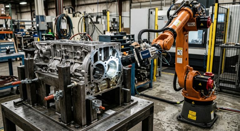
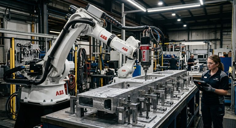
Robotic milling with parametric toolpaths
Robotic milling connects parametric surface or component geometry with material-removal paths.
The workflow may include:
- roughing and finishing strategies;
- tool-axis control;
- stepover and stepdown parameters;
- machining boundaries;
- collision avoidance;
- entry and exit movements;
- tool-change logic;
- workpiece repositioning or external-axis coordination.
Robot flexibility allows access from multiple directions and can support large workpieces. The articulated arm is generally less rigid than a dedicated CNC machine, so cutting forces, tool length, robot posture and fixture stability must be controlled.
A parametric model can help adapt machining paths to different components, but it cannot remove the mechanical limits of the robot and spindle system.
Explore related process guidance in the Milling Robots section.
Parametric workflows for robotic additive manufacturing
In additive fabrication, the parametric model can control both the final geometry and the deposition strategy.
Variables may include:
- layer height;
- bead width;
- deposition direction;
- tool orientation;
- material flow;
- robot speed;
- path overlap;
- cooling or curing time;
- support and reinforcement strategy.
Multi-axis robot movement can allow deposition on non-horizontal surfaces or around an existing component. This creates possibilities beyond conventional planar layer stacking.
It also increases process complexity. Gravity, material flow, nozzle distance, collision risk and local cooling conditions change as the tool orientation changes.
The parametric design system must therefore generate paths that respond to both geometry and material behaviour.
Further applications are available in the 3D Printing Robots category.
Parametric robotic assembly
Parametric models can also generate placement and assembly instructions for components such as bricks, timber elements, panels or customised modules.
The system may define:
- the position and orientation of every part;
- assembly sequence;
- gripping points;
- approach directions;
- connection or adhesive operations;
- temporary support conditions;
- coordination between several robots or operators.
A component that is correctly positioned in the final model may still be impossible to insert during assembly. The path to the final position must remain accessible, and previously placed elements must not block the robot or gripper.
Assembly sequence is therefore a design variable rather than an operational detail added at the end.
How material feedback can modify the parametric model
Digital models begin with assumptions about the physical process. Testing may show that the real material behaves differently.
Examples include:
- timber springing back after cutting or forming;
- clay deforming under its own weight;
- concrete deposition spreading beyond the intended bead width;
- composite fibres shifting during winding;
- machined surfaces showing vibration or tool marks;
- components accumulating assembly tolerance.
Measurements from test pieces, scanners, vision systems or force sensors can be used to adjust the parametric model or process parameters.
This creates a feedback loop:
- the model generates geometry and process data;
- the robot produces a physical result;
- the result is inspected or scanned;
- deviations are analysed;
- the model or process parameters are updated;
- the next fabrication cycle uses the revised logic.
The objective is not always to eliminate every variation. In some creative processes, measured material behaviour can become an intentional input into the next design version.
What are the limitations of parametric robotic fabrication?
Parametric workflows create flexibility, but they can also hide complexity.
- A flexible model can produce invalid geometry. Every permitted parameter range must be tested.
- Design updates can break downstream logic. Toolpaths, fixtures or postprocessors may depend on assumptions that are no longer valid.
- Simulation remains an approximation. It may not reproduce tool deflection, material flow, vibration or calibration errors.
- Robot repeatability is not total process accuracy. Tooling, workholding and material response influence the result.
- Large programs may exceed controller or communication limits. Path density and file structure must be managed.
- Software interoperability can be fragile. Plugin, controller and postprocessor versions must remain compatible.
- Technical knowledge is still required. Visual programming does not remove the need to understand kinematics, fabrication and safety.
- Parameter changes require governance. Teams must know which variables may be edited and who approves changes.
A parametric definition should not be considered complete only because it generates attractive geometry. It must generate predictable and verifiable production information.
Why version control matters in parametric robotics
Parametric robotic projects may contain several connected files:
- the Rhino model;
- Grasshopper definitions;
- custom scripts or plugins;
- tool and robot models;
- simulation files;
- postprocessor versions;
- controller programs;
- calibration data;
- material and process parameters.
A change in one layer may affect several downstream outputs. The team should be able to identify which model, definition, robot program and cell configuration produced each physical component.
Version control is particularly important when:
- several designers edit the same system;
- multiple component variants are produced;
- the controller or software is updated;
- tooling is changed;
- production is repeated after a long interval;
- research results must be reproduced.
Without traceability, a successful prototype may be difficult to reproduce because the exact digital and physical conditions are unknown.
Can refurbished robots support parametric fabrication?
Refurbished industrial robots can support parametric design, research and digital fabrication when the selected controller, communication options and mechanical condition match the required workflow.
The robot’s age does not by itself determine whether parametric programming is possible. The evaluation must consider:
- controller generation;
- supported programming language;
- available communication interfaces;
- offline programming and simulation compatibility;
- program and memory limits;
- external-axis support;
- installed software options;
- availability of system backups and documentation;
- spare parts and technical support.
Older controllers may remain suitable for offline-generated programs but may offer fewer options for high-frequency communication, sensor integration or real-time control.
A refurbished robot should therefore be selected according to the intended software and process architecture, rather than purchased first and adapted later without verifying compatibility.
RHTS provides new and refurbished industrial robots that can be evaluated for milling, additive manufacturing, architectural research and other parametric fabrication workflows.
How to evaluate a parametric robotic fabrication project
Parametric robotics evaluation framework
- Design logic: Which relationships and parameters generate the geometry?
- Fabrication process: Will the robot mill, print, cut, place, form or assemble?
- Toolpath logic: How will position, orientation and sequence be generated?
- Robot model: Does the arm provide sufficient reach, payload and movement capability?
- Controller: Can it execute the required program structure and process commands?
- Simulation: Can reach, collision, singularities and external axes be verified?
- Calibration: How will the digital and physical coordinate systems be aligned?
- Material: Which behaviours cannot be predicted from geometry alone?
- Validation: How will physical output be measured and approved?
- Traceability: Can every component be connected to its model and robot-program version?
If these layers are treated separately, the workflow may remain dependent on manual correction and specialist intervention for every new component.
When they are connected systematically, parametric design becomes a practical method for controlling robotic variation and production.
Frequently asked questions
What is parametric design in robotic fabrication?
Parametric design defines geometry through editable variables and relationships. In robotic fabrication, those rules can also generate toolpaths, tool orientations, component positions and production sequences.
Can Grasshopper program an industrial robot?
Grasshopper can generate robot targets and process data through suitable components, plugins or custom scripts. The paths must still be simulated, postprocessed for the specific controller and validated in the physical cell.
Can a Rhino model be sent directly to a robot?
Not as a complete fabrication process. The geometry must first be converted into ordered robot targets, orientations, speeds, process commands and controller-compatible code.
Why is robot simulation necessary?
Simulation checks whether paths are reachable and helps identify collisions, joint limits, singularities, unstable configurations and external-axis requirements before execution.
What is a robot postprocessor?
A postprocessor converts generic path information into the programming language, motion commands and file structure required by a specific robot controller.
Can parametric design produce unique components automatically?
Yes, when the model generates both component geometry and valid fabrication data. The workflow must ensure that every permitted variation remains within robot, tooling, material and quality limits.
Can refurbished robots work with parametric design software?
They can when the controller, postprocessor, communication options and simulation environment are compatible. Compatibility must be checked for the exact robot and controller generation.
Does a robot guarantee that the physical result matches the digital model?
No. Calibration, robot stiffness, tooling, fixtures, material behaviour and process forces all affect the physical result.
Parametric design becomes fabrication only when the complete system is connected
Parametric design and robotics create a direct relationship between digital rules and physical production. A change in geometry can update a family of components, their toolpaths and their robot targets without rebuilding every element manually.
But the robot cannot execute design intent from geometry alone. The process must define how the tool moves, how the robot is configured, how the material behaves and how the digital coordinate system corresponds to the real cell.
The strongest workflows connect design, process planning, simulation, postprocessing, calibration and inspection. They allow fabrication constraints to influence the model and physical results to improve the next design iteration.
This is where parametric robotic fabrication becomes more than automated form-making. It becomes a traceable production system capable of generating controlled variation while preserving technical feasibility.
Explore related analysis in the Robot Art & Architecture section, or read how robotic architecture changes design, fabrication and authorship.
Studios, research teams and fabrication laboratories can also contact RHTS to discuss the robot, controller, reach, payload, external axes and software requirements of a parametric fabrication project.