English
 Italiano
 Українська
 Русский
 Español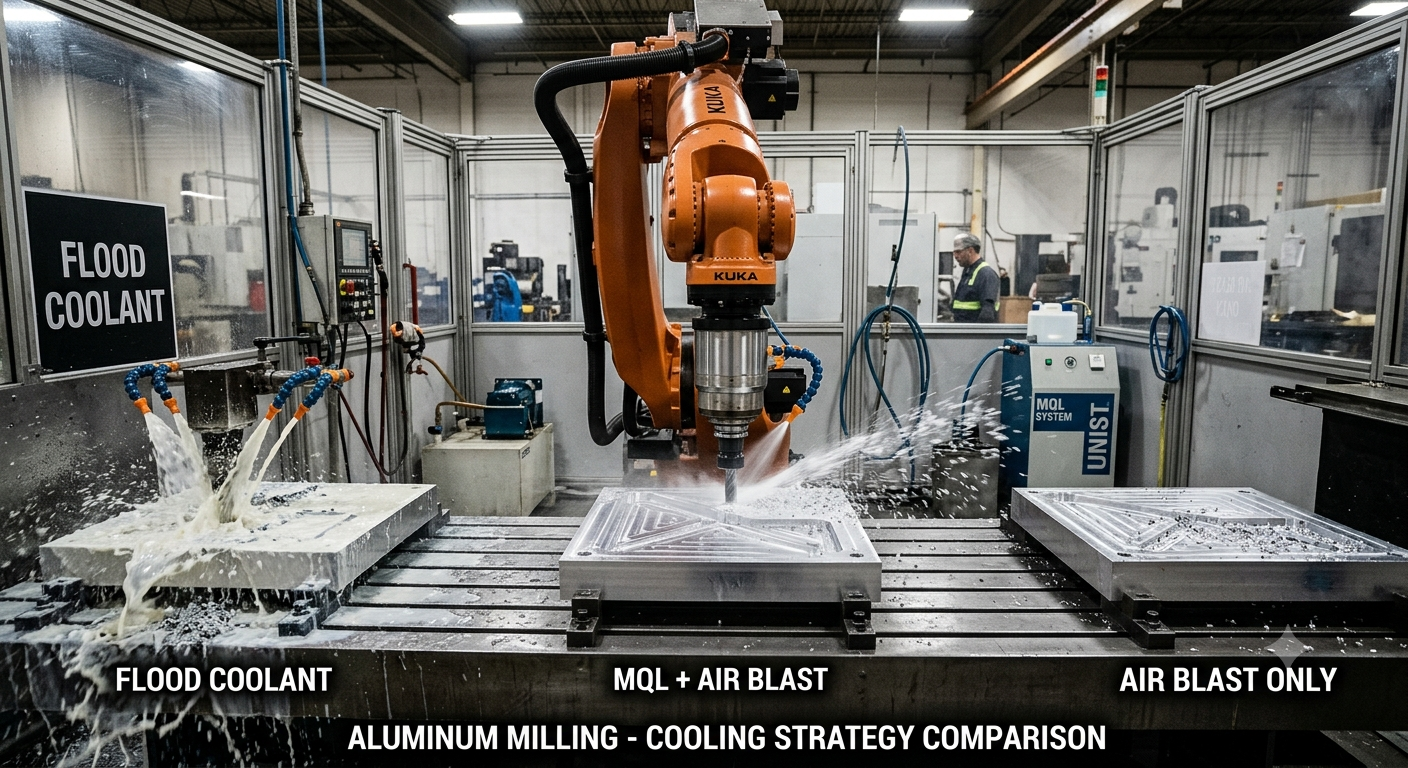

Air blast, MQL, or flood coolant? Learn how to select the right system for machining stability, cleanliness, tool life, and long-term cell performance.
Choosing the right robotic milling cooling system for aluminum requires more than deciding how to reduce cutting temperature. The selected method also affects chip evacuation, tool lubrication, spindle cleanliness, fluid containment, extraction requirements, maintenance procedures, and operator safety.
Aluminum is generally considered a machinable material. However, problems can quickly appear when a robotic cell is pushed toward higher material removal rates, shorter cycle times, longer tool engagement, or more demanding surface-finish targets.
In many installations, an unsuitable cooling system does not cause an immediate breakdown. Instead, performance gradually declines. Chips begin to recirculate, aluminum adheres to the cutting edge, surface defects appear, filters require more attention, and cleaning operations become increasingly time-consuming.
At Robotic Hi-Tech Solutions, cooling is treated as part of the complete machining process rather than as an accessory added after the spindle and robot have already been selected. A reliable aluminum milling process must control three connected factors: heat, chips, and contamination.
Why Robotic Milling Cooling Is Different from CNC Cooling
Traditional CNC machining centers usually operate inside rigid, purpose-built enclosures. Robotic milling cells, by contrast, may have larger working volumes, moving linear axes, positioners, external spindle equipment, or partially open architectures.
These differences change how chips, air, lubricant, and coolant travel through the production area. Consequently, the cooling system must be compatible with the entire cell architecture.
Important design considerations include:
- How aluminum chips are generated and dispersed
- Whether fluids can be contained inside the machining area
- How operators access the robot, spindle, fixture, and workpiece
- Where extraction ducts and chip collection systems are located
- How the floor and surrounding equipment are protected
- Whether the robot moves across a linear axis
- How frequently the cell must be cleaned and maintained
A cooling method that works inside a compact CNC machine may become difficult to manage inside a large robotic cell. Therefore, the decision must account for both cutting performance and system integration.
Air Blast for Light Robotic Aluminum Milling
Compressed air is usually the simplest cooling and chip-removal method. A nozzle directs a continuous air stream toward the cutting zone to prevent chips from remaining around the tool.
Air blast is particularly suitable for:
- Light trimming operations
- Shallow milling passes
- Thin-wall aluminum components
- Intermittent cutting
- Cells that process both composites and aluminum
- Applications where fluid contamination must be minimized
Advantages of air blast
Air systems are relatively easy to integrate and do not require coolant tanks, pumps, drainage channels, or fluid filtration. They also help maintain a cleaner fixture and reduce the amount of liquid that reaches the robot, cables, floor, and surrounding equipment.
For operations that generate limited heat, a correctly positioned air nozzle can provide effective chip evacuation without increasing cell complexity.
Limitations of air blast
Compressed air offers limited thermal control and almost no lubrication at the tool–material interface. It may therefore be insufficient during deep milling, long tool engagement, aggressive roughing, or operations with high material removal rates.
Another concern is chip dispersion. High-pressure air can spread fine aluminum particles across a large area when the enclosure and extraction system are not properly designed.
Air blast is therefore best considered a chip-management solution for light-duty machining rather than a complete answer for demanding aluminum removal.
MQL for Robotic Milling of Aluminum
Minimum Quantity Lubrication, commonly known as MQL, combines compressed air with a controlled quantity of lubricant. The system delivers a fine lubricant stream directly toward the cutting edge.
MQL can provide a practical balance between dry machining and conventional flood coolant. It improves lubrication while using significantly less fluid than a full flood system.
Common benefits include:
- Reduced friction at the cutting edge
- Lower risk of aluminum adhesion
- Improved chip evacuation
- Limited fluid consumption
- Less liquid accumulation around the cell
- Simpler cleanup compared with flood coolant
When MQL is a suitable choice
MQL is often effective when the machining process generates moderate heat, surface quality is important, and a fully sealed enclosure is impractical. It is particularly useful for medium-duty aluminum milling, trimming, routing, and finishing operations.
However, the application method must remain consistent. Nozzle orientation, flow settings, lubricant selection, cutting-tool geometry, and machining parameters all influence performance.
Aerosol control and extraction
MQL does not eliminate the need for environmental controls. The process can create airborne lubricant particles, especially when high spindle speeds and compressed air are used.
The cell should therefore include appropriate extraction and filtration. Designers must also evaluate nozzle positioning so that lubricant reaches the tool instead of being dispersed through the enclosure.
When correctly integrated, MQL is frequently the most balanced cooling strategy for robotic milling of aluminum in cells where cleanliness and process performance are equally important.
For many medium-duty aluminum applications, MQL provides a practical robotic milling cooling solution because it combines lubrication, chip evacuation, and limited fluid consumption.
Flood Coolant for High Material Removal Rates
Flood coolant delivers a continuous volume of fluid to the cutting zone. It provides stronger heat removal than either air blast or MQL and can support more demanding machining conditions.
Flood cooling may be appropriate when the application involves:
- Deep cutting passes
- Extended tool engagement
- High material removal rates
- Long machining cycles
- Strict surface-finish requirements
- Processes that generate substantial cutting heat
Benefits of flood coolant
The large fluid volume helps remove heat from the cutting area while carrying chips away from the tool. It can also reduce built-up edge formation and provide more consistent cutting conditions during long cycles.
For heavy aluminum roughing, flood coolant may deliver the most stable thermal environment. Nevertheless, the machining benefit must be evaluated against the additional integration requirements.
Integration challenges in robotic cells
A flood system requires more than installing a pump and several nozzles. The complete cell may need sealed guarding, sloped surfaces, drainage channels, coolant tanks, pumps, filters, chip separators, mist extraction, and accessible cleaning points.
Designers must also prevent fluid from reaching sensitive robot components, electrical connections, linear-axis equipment, or areas outside the protected machining zone.
When containment is inadequate, coolant can accumulate on the floor, increase slip hazards, contaminate nearby equipment, and create additional maintenance work. For that reason, flood cooling should only be selected when the cell architecture can properly support it.
Flood coolant becomes a suitable robotic milling cooling method when high material removal rates create more heat than air blast or MQL can control consistently.
How Cooling Affects Built-Up Edge and Tool Life
Aluminum can adhere to the cutting edge under unsuitable machining conditions. This accumulation, known as built-up edge, changes the effective geometry of the tool and can reduce cutting consistency.
Common consequences include:
- Higher cutting forces
- Poorer surface finish
- Dimensional variation
- Irregular chip formation
- Premature tool wear
- Greater risk of tool damage
Cooling and lubrication can help reduce adhesion, but they cannot correct every process problem. Tool geometry, coating, spindle speed, feed rate, depth of cut, tool stick-out, and chip load must also be optimized.
The cooling system should therefore support a validated cutting strategy rather than compensate for unsuitable machining parameters.
Chip Evacuation and Surface Quality
Removing heat is only part of the process. The system must also prevent chips from returning to the cutting zone.
When aluminum chips remain on the workpiece, the tool may cut them again during subsequent passes. This chip recutting increases heat, damages the cutting edge, and may leave visible scratches on the finished surface.
The risk is especially important during finishing operations on large molds, panels, patterns, and aerospace components. Even when dimensional accuracy remains acceptable, recirculating chips can reduce the visual quality of the surface.
Nozzle direction should follow the tool orientation and the expected chip trajectory. In multi-axis machining, fixed nozzles may not reach the cutting area throughout the complete robot path. Adjustable, spindle-mounted, or multi-nozzle systems may therefore be required.
Spindle Protection and Cell Cleanliness
Cooling system selection also affects the spindle and its surrounding components. Aluminum chips can accumulate around the spindle nose, tool holder, automatic tool changer, sensors, cable connections, and protective covers.
Fluid and chip ingress should be considered during spindle specification. The spindle sealing arrangement, tool-change mechanism, air-purge system, and maintenance instructions must all be compatible with the selected cooling method.
For cells that use automatic tool changing, the design should prevent coolant or chips from entering the tool interface. Contamination in this area may affect clamping reliability, tool runout, and repeatability.
Regular inspection points should be accessible without requiring extensive disassembly of the robotic cell.
Safety, Air Quality, and Maintenance Requirements
Each cooling method creates different safety and maintenance responsibilities. Air blast can spread chips, MQL can generate airborne lubricant particles, and flood systems can create fluid leakage or slippery surfaces.
The risk assessment should consider:
- Airborne chips and mist
- Operator exposure during loading and maintenance
- Slip hazards around the cell
- Fluid contact with electrical equipment
- Filter replacement intervals
- Coolant concentration and condition
- Waste collection and disposal
- Fire and combustible-dust considerations where applicable
Machine guarding, extraction, housekeeping, and maintenance procedures should be incorporated into the cell risk assessment. General machine-safety guidance is available from the Occupational Safety and Health Administration.
The best-performing cooling system is not necessarily the one with the greatest fluid flow. It is the system that the production team can operate, inspect, and maintain consistently.
How to Select the Right Cooling Strategy
Before selecting a cooling strategy for robotic milling of aluminum, engineers should define the actual machining conditions rather than relying on a general preference for air, MQL, or flood coolant.
The evaluation should include:
- Material removal rate: Heavy roughing usually generates more heat than trimming or finishing.
- Tool engagement: Deep or continuous engagement may require stronger lubrication and cooling.
- Surface-finish target: Finishing operations require effective control of chip recirculation.
- Machining duration: Long cycles can create gradual thermal accumulation.
- Cell enclosure: Open and partially enclosed systems may not support flood coolant.
- Robot configuration: Linear axes and positioners can complicate fluid containment.
- Extraction capacity: Air and MQL systems may require enhanced particle or mist extraction.
- Maintenance resources: Flood coolant demands fluid monitoring, filtration, and structured cleaning.
- Spindle compatibility: The spindle, seals, tool interface, and accessories must tolerate the selected method.
- Environmental requirements: Fluid use, waste handling, compressed-air consumption, and workplace exposure must be reviewed.
In some applications, a combined approach may be appropriate. For example, a cell may use air blast during light trimming and MQL during longer finishing passes. The final configuration should be validated through machining trials under realistic production conditions.
Checklist Before Selecting the Cooling System
- ✓ Target material removal rate has been defined
- ✓ Cutting-tool geometry and machining parameters have been reviewed
- ✓ Surface-finish requirements are documented
- ✓ Tool engagement and expected heat generation are understood
- ✓ The chip evacuation path has been analyzed
- ✓ Nozzle access has been checked across the complete robot path
- ✓ Cell enclosure and fluid containment have been evaluated
- ✓ Spindle and tool-changing components are compatible with the cooling method
- ✓ Mist or particle extraction requirements have been defined
- ✓ Maintenance capacity and cleaning procedures have been reviewed
- ✓ Environmental and workplace-safety requirements have been confirmed
- ✓ The proposed solution has been tested under representative cutting conditions
Conclusion
A reliable robotic milling cooling strategy must control temperature, chip evacuation, lubrication, contamination, and maintenance requirements as part of the complete cell design.
There is no universal system that is ideal for every application. The correct choice depends on material removal rate, tool engagement, surface-finish requirements, chip behavior, enclosure design, spindle compatibility, extraction capacity, and maintenance resources.
When the cooling system is engineered together with the robot, spindle, tooling, fixture, guarding, and extraction equipment, it becomes a source of machining stability rather than an operational complication.
Robotic Hi-Tech Solutions designs robotic milling cells in which cooling, chip evacuation, spindle protection, and maintenance access are evaluated as part of the complete machining process. Contact our engineering team to discuss the most suitable configuration for your aluminum application.
FAQ’s
1. Is compressed air enough for robotic milling of aluminum?
Compressed air may be sufficient for light trimming, shallow milling, and intermittent cutting. However, it usually provides inadequate lubrication and heat removal for deep cuts, long tool engagement, or aggressive material removal.
2. Does MQL improve tool life when milling aluminum?
MQL can improve tool life by reducing friction and limiting aluminum adhesion to the cutting edge. Its effectiveness depends on correct nozzle positioning, lubricant delivery, tool geometry, and machining parameters.
3. Is flood coolant necessary for high-speed aluminum milling?
Flood coolant is not automatically necessary for every high-speed operation. It becomes more relevant when high spindle speed is combined with substantial tool engagement, long cycles, deep cuts, or high material removal rates.
4. What is the cleanest cooling method for a robotic milling cell?
Air blast is generally the cleanest method because it does not introduce cutting fluid. Nevertheless, it can spread chips across the cell. MQL uses limited lubricant and may provide a cleaner alternative to flood coolant when suitable extraction is installed.
5. Can MQL be used in an open robotic cell?
MQL can be integrated into partially open cells, but mist and airborne lubricant particles must be controlled. Local extraction, filtration, guarding, and proper nozzle placement are essential.
6. How does cooling affect the surface finish of aluminum parts?
Cooling and lubrication help prevent built-up edge, excessive heat, and chip recutting. These factors directly influence surface roughness, scratches, dimensional consistency, and the appearance of finishing passes.
7. Can the same robotic cell use more than one cooling method?
Yes. Some cells combine air blast and MQL or use different settings for roughing and finishing. However, each operating mode must be included in the cell controls, safety assessment, maintenance plan, and process validation.
8. What should be tested before approving the cooling system?
Testing should confirm tool life, chip evacuation, surface finish, thermal behavior, nozzle coverage, extraction performance, spindle cleanliness, fluid containment, and maintenance requirements under representative production conditions.