English
 Italiano
 Українська
 Русский
 Español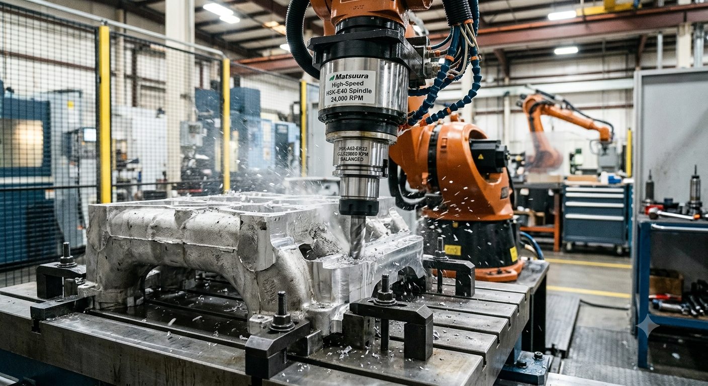

Robotic milling tool holders are critical components that directly influence machining stability, spindle performance, vibration levels, and surface finish. Selecting the correct tool holder and balancing system helps reduce runout, improve machining accuracy, and extend spindle life in large-format robotic milling applications.
Why Robotic Milling Tool Holders Are Critical for High-Speed Machining
When vibration marks, poor surface finish, or inconsistent dimensional accuracy appear in a robotic milling process, the first assumption is often that the robot lacks rigidity or that the cutting parameters need adjustment. While these factors certainly influence machining performance, they are not always the primary cause.
In many cases, the source of instability is much closer to the cutting edge. The interface between the spindle and the tool holder—and the way the complete rotating assembly has been balanced—has a direct impact on machining quality.
In high-speed robotic milling, even microscopic deviations in concentricity or imbalance can generate significant centrifugal forces. These forces become increasingly problematic when machining large aluminum structures, composite molds, aerospace components, or other large-format parts where long tool reach and variable robot stiffness amplify dynamic behavior.
Because every machining error accumulates throughout the process, small imperfections at the spindle interface can eventually lead to unacceptable dimensional deviations, premature tool wear, poor surface quality, and shortened spindle life.
At Robotic Hi-Tech Solutions, spindle integration goes far beyond mechanical installation. We engineer the complete machining system by optimizing tool holder selection, runout control, balancing quality, and spindle configuration to ensure long-term process stability and repeatable machining accuracy.
Why Tool Holder Selection Matters More in Robotic Milling Than in Traditional CNC Machines
Unlike conventional CNC machining centers, industrial robots exhibit posture-dependent stiffness. As the robot changes position within its working envelope, structural rigidity also changes. This makes robotic machining significantly more sensitive to vibration generated by the rotating assembly.
For this reason, the tool holder becomes far more than a simple connection between the spindle and the cutting tool. It becomes an essential component of the machine’s dynamic stability.
An improperly selected or poorly balanced tool holder can:
- Increase vibration throughout the machining process.
- Accelerate spindle bearing wear.
- Reduce cutting tool life.
- Create chatter during finishing operations.
- Lower surface finish quality.
- Decrease dimensional repeatability.
- Increase maintenance costs over time.
As spindle speeds exceed 18,000 to 24,000 rpm, dynamic behavior becomes increasingly sensitive, making precision tool holder selection one of the most important engineering decisions in the entire robotic milling cell.
Choosing the Right Tool Holder Interface
Selecting the appropriate spindle interface depends on machining speed, rigidity requirements, tooling strategy, and spindle design. Although several standards exist, two interface families dominate industrial robotic milling applications.
HSK Tool Holders
HSK (Hollow Shank Taper) systems are generally considered the preferred solution for high-speed robotic milling because they provide excellent repeatability and superior dynamic performance.
Typical applications include:
- High-speed finishing.
- Precision machining.
- Composite trimming.
- Aerospace aluminum components.
- Large mold finishing.
Key advantages include:
- Dual-contact clamping between taper and flange.
- Excellent concentricity.
- Higher rigidity under cutting loads.
- Superior repeatability after multiple tool changes.
- Outstanding performance at elevated spindle speeds.
Because the hollow shank expands slightly under centrifugal force, the interface maintains excellent contact even at very high rotational speeds.
ISO and BT Tool Holders
ISO and BT taper systems remain widely used across industrial machining because they offer broad tooling compatibility and competitive acquisition costs.
They are commonly selected for:
- Medium-speed milling operations.
- General-purpose machining.
- Budget-conscious robotic cells.
- Applications requiring compatibility with existing tooling inventories.
Although ISO and BT holders continue to deliver reliable performance, HSK systems usually provide greater stability, improved repeatability, and lower vibration levels in demanding high-speed robotic finishing applications.
The optimal choice ultimately depends on spindle specifications, cutting strategy, required tolerances, and the materials being machined.
Runout Control: The Hidden Variable Behind Machining Quality
Tool holders for high-speed robotic milling must maintain excellent concentricity to minimize runout and improve machining accuracy.
Runout refers to the radial deviation of the cutting tool as it rotates around its axis. Even extremely small deviations can significantly affect machining quality during high-speed robotic milling.
Excessive runout influences nearly every aspect of the cutting process, including:
- Dimensional accuracy.
- Surface finish consistency.
- Tool wear.
- Cutting forces.
- Machining repeatability.
For precision finishing operations, Total Indicated Runout (TIR) is typically maintained below 0.01–0.02 mm, depending on the material being machined and the required tolerance.
Several factors contribute to excessive runout:
- Worn collets.
- Contaminated contact surfaces.
- Improper assembly torque.
- Damaged tool holders.
- Poor-quality cutting tools.
Because industrial robots naturally possess lower structural stiffness than heavy gantry machining centers, excessive runout quickly becomes visible through vibration marks, dimensional inaccuracies, and reduced tool life.
Dynamic Balancing Is Essential for High-Speed Spindles
As spindle rotational speed increases, balancing quality becomes one of the most important factors affecting machining stability.
Proper balancing is essential when using robotic milling tool holders at spindle speeds above 18,000 rpm.
Dynamic imbalance generates centrifugal forces that grow exponentially with rotational speed. Even a very small mass imbalance can create significant vibration once spindle speeds exceed 20,000 rpm.
Balancing quality is generally classified according to ISO 21940, with balancing grades such as G2.5 or G6.3 commonly used for rotating assemblies.
For most high-speed robotic milling applications, engineers typically recommend:
- Balancing grade G2.5.
- Balancing the complete tool-and-holder assembly rather than each component individually.
- Performing balancing at the intended operating speed whenever possible.
- Verifying balance after replacing cutting tools.
Proper balancing delivers several long-term advantages:
- Lower vibration levels.
- Improved surface finish.
- Longer spindle bearing life.
- Extended cutting tool life.
- Higher machining precision.
- Greater process repeatability.
Balancing quality is commonly evaluated according to ISO standards, including ISO 21940 for rotating machinery.
Integrating Tool Holders with Automatic Tool Changers (ATCs)
Many high-speed robotic milling cells use Automatic Tool Changers (ATCs) to maximize productivity and reduce manual intervention. While ATCs significantly improve efficiency, they also introduce additional variables that can affect machining accuracy if the tooling system is not properly engineered.
Every automatic tool change represents another opportunity for small deviations to occur. Individually, these deviations may appear insignificant, but over hundreds or thousands of machining cycles they can accumulate and negatively impact process stability.
Potential issues introduced during automatic tool changes include:
- Dust, chips, or coolant contamination on the taper contact surfaces.
- Minor variations in tool seating.
- Clamping force inconsistencies.
- Tolerance stack-up between spindle, holder, and cutting tool.
- Progressive wear of retention knobs and clamping mechanisms.
To maintain consistent machining quality, tool holders should always be fully compatible with the spindle interface and the ATC system. Equally important, preventive maintenance schedules should include routine inspection of taper cleanliness, pull studs, collets, clamping force, and tool holder condition.
Well-maintained tooling systems deliver more repeatable tool changes, lower vibration levels, and longer spindle service life.
Automatic tool changers must preserve the positioning accuracy of tool holders for high-speed robotic milling throughout thousands of machining cycles.
Engineering Best Practices for Tool Holder Selection
Selecting robotic milling tool holders requires evaluating spindle compatibility, balancing quality, rigidity, and tooling strategy.
Robotic milling tool holders are fundamental to achieving stable, repeatable, and accurate machining.
Before approving a tooling strategy, engineering teams should evaluate several key factors:
- Match the tool holder type to the spindle manufacturer’s specifications.
- Use premium tool holders with certified concentricity for finishing operations.
- Keep tool overhang as short as possible to minimize deflection.
- Balance every tool-and-holder assembly at the intended operating speed.
- Measure Total Indicated Runout (TIR) after every critical tool assembly.
- Replace worn collets before they begin affecting machining quality.
- Clean spindle tapers and tool holders before every installation.
- Document balancing data and maintenance history for traceability.
Applying these practices helps improve machining consistency while reducing unplanned downtime, tooling costs, and premature spindle maintenance.
Conclusion
Tool holders for high-speed robotic milling play a fundamental role in achieving stable, repeatable, and accurate machining.
In high-speed robotic milling, the tool holder is far more than a mechanical connector. It is a critical component that directly influences machining precision, spindle reliability, vibration levels, and overall process stability.
Choosing the correct interface, minimizing runout, and dynamically balancing the complete rotating assembly allow manufacturers to achieve better surface finishes, tighter dimensional tolerances, longer tool life, and improved repeatability—especially when machining large aluminum structures, composite components, molds, and other demanding workpieces.
Successful robotic milling is built on a combination of robot performance, spindle quality, tooling strategy, and sound engineering practices. Optimizing the spindle interface is one of the most effective ways to maximize productivity while protecting long-term equipment investment.
Why Work with Robotic Hi-Tech Solutions?
At Robotic Hi-Tech Solutions, we design complete robotic milling systems that go beyond robot selection. Our engineering team optimizes spindle integration, tooling strategies, fixture design, robot programming, and process validation to deliver stable, repeatable, and high-performance machining solutions for large-format manufacturing.
Whether your application involves composite materials, aluminum, plastics, or advanced engineering materials, we help ensure that every component of the machining system contributes to maximum productivity and machining accuracy.
FAQ’s
1. Is HSK always the best choice for robotic milling?
Not necessarily. HSK tool holders generally provide superior performance for high-speed machining because of their dual-contact design and excellent repeatability. However, ISO and BT systems remain appropriate for many medium-speed applications depending on spindle specifications, tooling availability, and budget.
2. How much runout is acceptable in high-speed robotic milling?
For precision finishing operations, Total Indicated Runout (TIR) is typically maintained below 0.01–0.02 mm. The acceptable value ultimately depends on the workpiece material, cutting tool geometry, and required dimensional tolerances.
3. Is dynamic balancing necessary when machining aluminum?
Yes. Dynamic balancing is essential whenever spindle speeds are high, regardless of the material being machined. Proper balancing reduces vibration, protects spindle bearings, and improves surface finish.
4. How often should tool holders be inspected?
Tool holders should be inspected regularly as part of a preventive maintenance program. Inspection intervals depend on production volume, spindle speed, and operating conditions, but cleanliness, wear, and runout should be verified frequently.
5. Can poor tool holders reduce spindle life?
Absolutely. Excessive runout, imbalance, damaged tapers, or worn collets increase bearing loads and vibration, which can significantly shorten spindle service life and increase maintenance costs.
6. Should the cutting tool and holder be balanced separately?
No. For high-speed machining, the cutting tool and tool holder should be balanced together as a complete rotating assembly to achieve the highest level of dynamic stability.
7. Does tool overhang affect machining performance?
Yes. Longer tool overhang increases deflection and vibration while reducing rigidity. Keeping the tool as short as the application allows generally improves machining accuracy and surface quality.
8. What is the most common mistake when selecting tool holders?
Many manufacturers focus only on spindle compatibility while overlooking balancing quality, runout control, maintenance practices, and tooling condition. Evaluating the complete rotating system leads to far better machining performance.
Checklist Before Approving a Tooling Strategy
- Select the spindle interface based on operating speed and rigidity requirements.
- Verify compatibility between the spindle, tool holder, and ATC system.
- Measure runout after final tool assembly.
- Balance the complete tool-and-holder assembly.
- Confirm the balancing grade matches the intended spindle speed.
- Minimize tool overhang whenever possible.
- Inspect collets, pull studs, and taper surfaces regularly.
- Establish a documented preventive maintenance schedule.
Ready to Improve Your Robotic Milling Performance?
Choosing the right tool holders and balancing strategy can significantly improve machining quality, extend spindle life, and reduce production costs. If you are designing or upgrading a robotic milling cell, Robotic Hi-Tech Solutions can help you engineer a complete machining solution tailored to your production requirements.
Contact Robotic Hi-Tech Solutions to help manufacturers select the best tool holders for high-speed robotic milling for demanding industrial applications.