English
 Italiano
 Українська
 Русский
 Español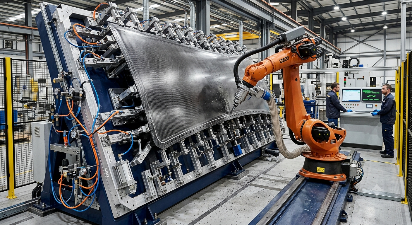

Engineering strategies to control springback, deflection, and machining stability in XXL composite and aluminum components.
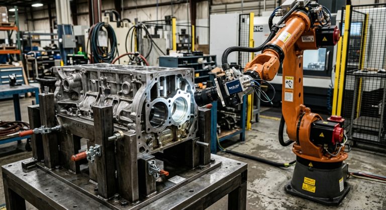
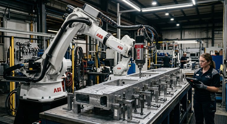
When engineers evaluate a robotic milling project, most attention is given to the robot, spindle, cutting tools, or CAM programming. While these elements are essential, another component has an equally significant impact: robotic milling fixturing. A properly engineered robotic milling fixturing system determines how stable and accurate the machining process will be.
Even the most accurate robot and the best machining strategy cannot compensate for an unstable workpiece. Poor fixture design can introduce vibration, dimensional inaccuracies, surface defects, and unexpected deformation throughout the machining process.
At Robotic Hi-Tech Solutions, fixture engineering is considered an integral part of robotic cell development rather than an accessory added at the end of the project. Proper fixturing ensures that large composite panels, aluminum structures, molds, and aerospace components remain stable throughout machining, helping manufacturers achieve consistent quality and repeatable production.
Why Robotic Milling Fixturing Is Critical
Unlike traditional CNC gantries, industrial robots do not maintain the same structural stiffness throughout their entire working envelope. Robot rigidity changes continuously depending on arm extension, joint configuration, payload, and tool orientation.
Because the robot itself is more compliant than a conventional machine tool, the stability of the workpiece becomes even more important. Any movement of the component can negatively affect machining accuracy.
Poor robotic milling fixturing may lead to:
- Dimensional variation after unclamping
- Surface chatter marks
- Edge trimming inconsistencies
- Reduced repeatability
- Poor surface finish
- Unexpected springback after machining
- Longer production cycles due to rework
In many applications, fixture quality directly determines whether robotic milling achieves production-level performance.
Every successful large-part machining project begins with properly engineered robotic milling fixturing.
Understanding Material Behavior Before Designing the Fixture
Every material responds differently to machining forces and clamping pressure. Designing an effective fixture begins with understanding these mechanical characteristics rather than applying a universal clamping strategy.
Composite Materials
Composite components often contain residual stresses generated during curing. If these stresses are unevenly released during machining, the component may deform after the clamps are removed, a phenomenon commonly known as springback.
Large aerospace structures, wind-energy components, marine parts, and automotive panels frequently require fixture systems that distribute support evenly across the entire workpiece.
Aluminum Structures
Although aluminum does not exhibit springback in the same way as composite laminates, thin-wall aluminum structures can deform when excessive clamping forces are applied. Even minor distortion during finishing operations may prevent the component from meeting dimensional tolerances.
Understanding material behavior before fixture design significantly reduces production risks.
Vacuum Versus Mechanical Clamping
Choosing the right workholding strategy depends on part geometry, machining forces, material characteristics, production volume, and dimensional requirements.
Vacuum Fixturing
Vacuum systems are commonly used when machining:
- Composite panels
- Carbon fiber laminates
- Thin sheet materials
- Large flat surfaces
Advantages include:
- Uniform pressure distribution
- Minimal localized deformation
- Fast loading and unloading
- Reduced fixture complexity
- Excellent accessibility for trimming operations
Limitations include:
- Dependence on effective sealing
- Reduced holding capability for heavy structural parts
- Sensitivity to leaks and damaged vacuum zones
Mechanical Clamping
Mechanical fixturing is generally preferred when machining:
- Large aluminum structures
- Heavy molds
- Structural aerospace components
- Parts exposed to significant cutting forces
Proper clamp positioning is essential. Concentrating force in only a few locations may create localized deformation that affects machining accuracy.
These methods are widely used in robotic milling setups, depending on the material and machining requirements.
Hybrid Fixturing Systems
Many advanced robotic milling cells combine vacuum systems with mechanical locating features and support stops. Hybrid solutions often provide the best balance between accessibility, rigidity, loading speed, and dimensional stability.
How to Minimize Springback During Robotic Milling
Springback is one of the most challenging issues encountered when machining large composite structures.
Residual stresses generated during manufacturing may remain hidden until machining removes material or clamping forces are released. If fixture constraints are not carefully engineered, the component can change shape after machining, even if measurements appear acceptable while it remains clamped.
Several engineering practices help minimize this risk:
- Support the complete geometry rather than only the outer edges.
- Distribute loads evenly across the fixture.
- Avoid excessive clamping forces.
- Use large contact surfaces instead of concentrated point loads.
- Validate clamping strategies through simulation whenever possible.
- Verify dimensional stability after unclamping during process validation.
These practices improve repeatability while reducing the likelihood of costly scrap or rework.
Reducing Vibration Through Better Fixture Design
When chatter appears during robotic milling, the robot is often blamed first. However, vibration frequently originates from insufficient workpiece support rather than from the robot itself.
Common sources of vibration include:
- Unsupported overhangs
- Long unsupported spans
- Flexible fixture bases
- Insufficient structural reinforcement
- Poor anchoring to the machine foundation
Even relatively small fixture deflections can become amplified during finishing operations, especially when using long cutting tools or machining thin-wall geometries.
Designing a rigid fixture base is therefore just as important as selecting the appropriate robot or spindle.
Optimizing robotic milling fixturing often eliminates vibration problems before machining parameters need to be adjusted.
Modular Versus Dedicated Fixtures for Large Robotic Milling
The ideal fixture configuration also depends on production volume, part variation, changeover frequency, and long-term manufacturing plans. Manufacturers generally choose between dedicated fixtures and modular systems.
Dedicated Fixtures
Dedicated fixtures are designed for one specific component or product family. They are commonly used in high-volume production environments where repeatability and short loading times are priorities.
The main advantages of dedicated fixtures include:
- Consistent part positioning
- High repeatability between production cycles
- Reduced setup and loading time
- Optimized support at critical machining areas
- Lower risk of operator-dependent positioning errors
However, dedicated fixtures require a greater initial investment and provide limited flexibility when part geometry changes.
Modular Fixtures
Modular systems use adjustable supports, rails, locating elements, vacuum zones, and mechanical clamps that can be repositioned for different components.
They are especially useful for:
- Low- and medium-volume manufacturing
- Prototype production
- Large components with similar geometries
- Applications with frequent product changes
- Robotic cells serving multiple machining processes
Although modular fixtures offer flexibility, they must still provide adequate rigidity. A fixture that is easy to reconfigure but lacks structural stability can introduce vibration and reduce machining accuracy.
For many large-format robotic milling applications, a semi-modular design offers the best compromise. The base structure remains rigid and permanent, while supports and locating elements can be adjusted for different part families.
Use Simulation to Validate Robotic Milling Fixturing
Fixture design should be validated before manufacturing begins, especially when working with XXL components, thin structures, composite laminates, or tight dimensional tolerances.
Engineering simulation can help determine whether the fixture will resist cutting forces without causing excessive deflection or localized stress.
Finite Element Analysis
Finite element analysis can be used to evaluate the structural behavior of the fixture and workpiece under simulated machining and clamping loads.
Depending on the application, the analysis may evaluate:
- Fixture base deformation
- Workpiece displacement
- Stress concentrations around clamps
- Support-point effectiveness
- Natural frequencies and vibration risk
- Clamping force distribution
Simulation does not eliminate the need for physical testing. However, it helps engineers identify weak areas before the fixture is manufactured, reducing costly modifications during commissioning.
Robot and Toolpath Simulation
The fixture must also be validated within the complete robotic cell layout. Supports and clamps should not interfere with the robot, spindle, cutting tool, extraction equipment, or measurement systems.
Offline simulation can verify:
- Robot reach throughout the machining area
- Tool access around clamps and supports
- Potential collisions with the fixture
- Required robot postures
- Cable and hose clearance
- Loading and unloading access
This integrated approach helps prevent situations in which a structurally effective fixture restricts the toolpath or forces the robot into unstable configurations.
Position Supports Near Machining Zones
Support location is one of the most important factors in robotic milling fixturing. Large parts should be supported as close as practical to the active machining area.
When the cutting tool operates far from a support point, the workpiece behaves like a flexible beam. The resulting deflection can cause dimensional errors and chatter, even when the robot follows the programmed path correctly.
For long panels or thin structures, adjustable supports may be required beneath different machining zones. In some applications, support elements can be repositioned between operations to maintain rigidity without obstructing the cutting tool.
Engineers should pay particular attention to:
- Thin-wall sections
- Large openings
- Free edges
- Long overhangs
- Areas where substantial material will be removed
- Locations requiring finishing passes
Supporting these regions can significantly improve surface quality and dimensional consistency.
Avoid Over-Constraining the Workpiece
A fixture must control part movement without forcing the component into an artificial shape. Excessive constraints can distort the workpiece during machining and produce inaccurate results after unclamping.
A well-engineered locating strategy typically controls the necessary degrees of freedom while allowing the component to settle naturally against its datum surfaces.
Common problems associated with over-constraining include:
- Clamping-induced deformation
- Residual stress redistribution
- Difficulty loading the component
- Inconsistent seating against datum points
- Geometry changes after unclamping
Using defined locating points and controlled clamping forces reduces these risks. Where appropriate, compliant supports may accommodate normal part variation without compromising stability.
Plan for Chips, Dust, and Fixture Maintenance
A fixture may perform well during initial testing but lose reliability if chips, composite dust, or coolant accumulate around locating surfaces and vacuum seals.
The fixture design should include sufficient access for inspection and cleaning. Drainage, extraction, and debris evacuation must also be considered during the engineering phase.
Important maintenance features include:
- Accessible vacuum channels
- Replaceable sealing materials
- Protected locating pins
- Easy-to-clean contact surfaces
- Accessible clamps and fasteners
- Inspection points for wear or damage
In composite machining, effective dust extraction is particularly important. Accumulated particles can affect sealing performance, interfere with datum surfaces, and create additional maintenance requirements.
Common Robotic Milling Fixturing Mistakes
Several recurring design errors can reduce the performance of a large robotic milling cell.
Supporting Only the Part Perimeter
Edge support may be insufficient for large panels. Central areas can vibrate or deflect under machining loads, especially during pocketing and finishing operations.
Applying Excessive Clamping Force
Higher clamping force does not always produce better stability. Excessive force can deform thin aluminum components and introduce stress into composite structures.
Ignoring Fixture Natural Frequencies
A structurally strong fixture can still vibrate if its natural frequency is excited by the spindle speed, tooth-passing frequency, or cutting process.
Designing the Fixture Separately from the Robot Cell
The fixture should not be engineered without considering robot reach, tool orientation, extraction equipment, safety systems, and operator access.
Failing to Measure the Part After Unclamping
A component may meet tolerances while clamped but change shape after release. Dimensional validation should therefore include measurements in the free state whenever springback or clamping distortion is possible.
9 Engineering Practices for Reliable Robotic Milling Fixturing
A robust fixture design should combine structural analysis, material knowledge, process planning, and practical production requirements.
- Analyze material behavior: Account for composite residual stress, aluminum wall thickness, and expected deformation.
- Define stable datum points: Create a repeatable locating strategy without over-constraining the part.
- Distribute clamping forces: Avoid concentrated loads and unnecessary tightening.
- Support critical machining zones: Place supports near thin sections, free edges, and finishing areas.
- Reinforce the fixture base: Ensure the fixture structure and foundation provide adequate rigidity.
- Evaluate vibration behavior: Assess natural frequencies and dynamic response where necessary.
- Validate robot accessibility: Confirm that clamps and supports do not obstruct machining paths.
- Plan for cleaning and maintenance: Provide access to vacuum seals, locating surfaces, and mechanical components.
- Measure after unclamping: Verify that the final component remains within tolerance in its released condition.
Checklist Before Approving a Fixturing Design
- Material behavior has been analyzed for composite or aluminum construction.
- Residual stress and springback risks have been evaluated.
- Clamping force distribution has been reviewed or simulated.
- Contact points do not create localized deformation.
- Unsupported spans and overhangs have been identified.
- Supports are positioned near critical machining zones.
- Fixture base rigidity has been verified.
- The fixture is anchored to an appropriate foundation.
- Robot reach and tool orientation have been simulated.
- Clamps do not interfere with machining paths.
- Loading and unloading access has been confirmed.
- Dust, chip, and debris evacuation has been considered.
- Maintenance and cleaning points are accessible.
- Final inspection includes measurements after unclamping.
Conclusion
In large-format robotic machining, fixturing is not a secondary mechanical detail. It is a fundamental process-control system that directly affects vibration, dimensional accuracy, surface finish, repeatability, and production reliability.
Effective robotic milling fixturing must support the workpiece without forcing it into an artificial geometry. It must distribute clamping pressure, reinforce flexible areas, remain rigid under cutting loads, and preserve access for the robot and spindle.
For large composite and aluminum components, the best results come from designing the robot, machining process, fixture, and cell layout as one integrated system. When these elements are engineered together, manufacturers can reduce deformation, prevent chatter, improve part quality, and protect the long-term return on investment of the robotic cell.
Investing in optimized robotic milling fixturing allows manufacturers to achieve higher quality, longer tool life, and more predictable production.
For additional guidance on machine safety and industrial equipment, visit the Occupational Safety and Health Administration (OSHA) .
Need a Stable Robotic Milling Solution for Large Parts?
Robotic Hi-Tech Solutions designs and integrates robotic milling cells for large and complex components. Our engineering approach considers robot selection, spindle integration, toolpaths, workpiece support, fixture rigidity, safety, and process validation as part of one complete system.
Contact Robotic Hi-Tech Solutions to evaluate the fixturing and machining requirements of your large-format robotic application.
FAQ’s
Does robotic milling require different fixturing from CNC machining?
Yes. Industrial robots have variable stiffness depending on their posture and arm extension. Therefore, workpiece support and fixture rigidity are particularly important in robotic milling applications.
Can vacuum fixturing hold large structural components?
Vacuum fixturing can work well for large panels and components with sufficient sealing area. However, heavy parts or applications with high cutting forces may require mechanical clamps, locating stops, or a hybrid system.
Is fixture simulation necessary for robotic milling?
Simulation is strongly recommended for XXL parts, flexible components, complex tool access, or tight tolerances. It can reveal fixture deflection, stress concentrations, collision risks, and unsupported regions before manufacturing begins.
How can a fixture reduce vibration during robotic milling?
A fixture reduces vibration by supporting the part near machining areas, minimizing unsupported spans, reinforcing the base structure, and preventing movement between the component and its locating surfaces.
What causes springback in composite parts?
Springback is commonly associated with residual stresses created during composite curing and manufacturing. Material removal or clamp release can redistribute these stresses and change the component geometry.
Can excessive clamping force deform an aluminum part?
Yes. Thin-wall and large aluminum structures can distort under excessive or uneven clamping pressure. Controlled force and distributed contact areas help reduce this risk.
Are modular fixtures accurate enough for production?
They can be, provided that the modular joints, support elements, and locating systems are sufficiently rigid and repeatable. Semi-modular designs are often effective for product families with similar geometries.
Should the part be inspected after it is removed from the fixture?
Yes. Measuring the part after unclamping helps identify springback or clamping-induced deformation that may not be visible while the component remains constrained.
Contact Robotic Hi-Tech Solutions to discuss the technical requirements of your robotic milling application.