English
 Italiano
 Українська
 Русский
 Español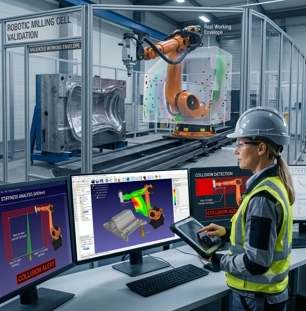

Validating the real robotic milling working envelope is essential before investing in a large-format machining cell. Catalog reach alone does not prove that a robot can mill a large part with the required stiffness, tool orientation, clearance, and process stability. For XXL components, the real working envelope must be engineered through simulation, collision analysis, stiffness evaluation, and layout validation.
A validated robotic milling working envelope helps engineers confirm not only where the robot can move but also where it can machine with stability and repeatable quality.
Selecting a robotic arm for a large milling application may seem simple at first. A company checks the robot reach, confirms the payload capacity, and assumes the cell will work. However, many robotic machining problems begin long before the robot is installed.
In large robotic milling, the usable workspace is not defined only by maximum reach. It is shaped by the robot base position, spindle geometry, tool length, workpiece size, fixture height, cutting forces, tool orientation, and surrounding equipment. If these variables are not validated together, the cell may technically reach the part but fail to machine it correctly.
At Robotic Hi-Tech Solutions, working envelope validation is one of the most important engineering steps in large robotic milling projects. It helps determine whether the proposed cell can operate reliably, safely, and efficiently from the first production cycle.
What Is the Real Robotic Milling Working Envelope?
The theoretical envelope is the maximum space the robot can reach according to the manufacturer’s specifications. The real robotic milling working envelope is the area where the robot can perform the machining process with acceptable stiffness, accessibility, orientation, clearance, and safety.
This real envelope depends on several technical factors:
- Tool length and spindle geometry
- Workpiece size and fixture height
- Robot base position and elevation
- Required tool orientations for 5-axis movement
- Collision margins around the robot, spindle, fixture, and guards
- Structural stiffness at extended positions
- Access for operators, maintenance, and part loading
In large robotic milling, working close to maximum extension can reduce stiffness. This affects surface finish, dimensional consistency, vibration behavior, and tool life. For this reason, reach must always be validated under real process conditions.
Step 1: Validate Reach with Offline Simulation
Before selecting the final architecture, offline simulation is mandatory. It allows engineers to test whether the robot can access every machining zone without relying on assumptions.
A complete simulation should include:
- Reachability maps
- Tool-path validation
- Singularity detection
- Collision analysis
- Robot, spindle, fixture, and guard clearance
- Axis movement and torque load evaluation
Simulation does not automatically guarantee feasibility, but it helps eliminate unrealistic layouts early. It also allows engineers to compare different robot positions, base heights, linear tracks, rotary positioners, and fixture concepts before committing to hardware.
For large robotic milling projects, offline simulation should be based on reliable robot data and validated engineering assumptions. Tools such as ABB RobotStudio or KUKA.Sim are commonly used to evaluate reach, tool paths, and collision risks before the final cell layout is approved.
Step 2: Map Stiffness Across the Workspace
Robot stiffness is not uniform across the full workspace. When the arm is extended horizontally or operates near its reach limits, structural compliance increases. In robotic milling, this can create vibration, reduced surface quality, and dimensional variation.
For this reason, the robotic milling working envelope must be evaluated not only by reach, but also by stiffness. A reachable position may still be unsuitable for finishing passes, aluminum milling, mold machining, or applications requiring tight tolerances.
Advanced stiffness validation may include:
- Position-dependent stiffness evaluation
- Cutting force estimation
- Dynamic behavior analysis
- Tool deflection assessment
- Review of machining quality at extreme positions
This step prevents the common mistake of designing a cell that works in a simulation but fails under real machining loads.
Step 3: Validate Layout, Fixture, and Base Design
Large parts introduce additional mechanical variables. Even if the robot can reach the tool path, the fixture, base plate, and surrounding structure must support the process.
Layout validation should review:
- Fixture rigidity and possible deflection
- Base plate design and anchoring
- Foundation flatness and stability
- Part loading and unloading access
- Maintenance access around the cell
- Safe distance from fences, guards, and auxiliary systems
A robot may reach a machining area but still operate in an unstable posture if the fixture height is incorrect. In large robotic milling, mechanical design and process engineering must be validated together.
Before approving the final investment, the robotic milling working envelope should be reviewed together with the fixture, spindle, tool length, and safety perimeter.
Step 4: Use Physical Pre-Validation When Risk Is High
For extremely large, complex, or high-value components, physical pre-validation may be justified. This does not always require a complete cell. In many cases, a partial mock-up is enough to verify the most critical areas.
Physical pre-validation may include:
- Simplified fixture replication
- Robot base height testing
- Tool clearance verification
- Access checks around critical part zones
- Review of operator and maintenance access
This step reduces uncertainty before final investment. It is especially useful when the workpiece is very large, the tolerance requirements are demanding, or the cost of redesign would be high.
Why Working Envelope Validation Protects ROI
Incorrect envelope estimation can create expensive problems after installation. These issues often require layout changes, fixture redesign, additional programming, or even a different robot architecture.
When the robotic milling working envelope is properly engineered, manufacturers reduce the risk of collisions, vibration problems, and costly layout changes after installation.
Poor validation may lead to:
- Unexpected collisions
- Reduced surface quality
- Lower-than-expected productivity
- Excessive vibration
- Restricted tool access
- Longer cycle times
- Costly redesign after installation
In large-format robotic milling, working envelope engineering determines whether the robotic solution becomes a practical alternative to a CNC gantry system. A well-validated cell can improve flexibility, reduce investment cost, and support large-part machining with a scalable architecture.
Conclusion
Validating the real robotic milling working envelope is not a design formality. It is a strategic safeguard that protects performance, safety, productivity, and return on investment.
For large robotic milling cells, reach, stiffness, accessibility, tool orientation, fixture design, and collision clearance must be evaluated together. When these factors are properly engineered, robotic milling can become a flexible and cost-effective solution for large and complex parts.
Robotic Hi-Tech Solutions helps manufacturers validate robotic milling architectures before investment, reducing technical risk and improving the probability of a successful installation.
FAQs
Does the robot manufacturer specify the reach enough?
No. Catalog reach does not include tool length, spindle geometry, fixture height, workpiece size, stiffness loss, or collision margins. The real working envelope must be validated under process conditions.
Can simulation replace physical validation?
In many projects, simulation is sufficient for early validation. However, high-risk XXL projects may require partial physical mock-ups to confirm clearance, base height, and access.
Does working envelope validation affect machining precision?
Yes. Robot stiffness changes across the workspace. If the robot mills near unstable or extended positions, vibration and dimensional variation may increase.
When should stiffness mapping be performed?
Stiffness mapping should be performed before final architectural approval, especially when machining aluminum, composites, molds, or large parts with demanding surface-quality requirements.
Can a linear axis improve the robotic milling working envelope?
Yes. A linear axis can improve access to large parts and reduce the need to work at extreme robot extension. However, it must also be validated for stiffness, accuracy, and collision risk.
What happens if the fixture height is not validated?
An incorrect fixture height can force the robot into unstable postures. This may reduce stiffness, increase vibration, limit tool orientation, and affect machining quality.
Why is collision analysis important in large robotic milling cells?
Collision analysis confirms that the robot, spindle, tool, fixture, guards, and surrounding equipment have enough clearance during the full machining cycle.
Should ROI be reviewed during envelope validation?
Yes. The final working envelope influences cycle time, productivity, redesign risk, and machining quality. These factors directly affect the return on investment of the robotic cell.
Checklist Before Final Architecture Approval
- Reachability map validated
- Tool length and spindle geometry integrated
- Collision analysis completed
- Singularity zones identified
- Stiffness evaluated at extreme positions
- Fixture height reviewed
- Base rigidity confirmed
- Maintenance access verified
- Layout reviewed with process requirements
- ROI scenario confirmed before investment
Contact Robotic Hi-Tech Solutions to discuss the technical requirements of your robotic milling application.