English
 Italiano
 Українська
 Русский
 Español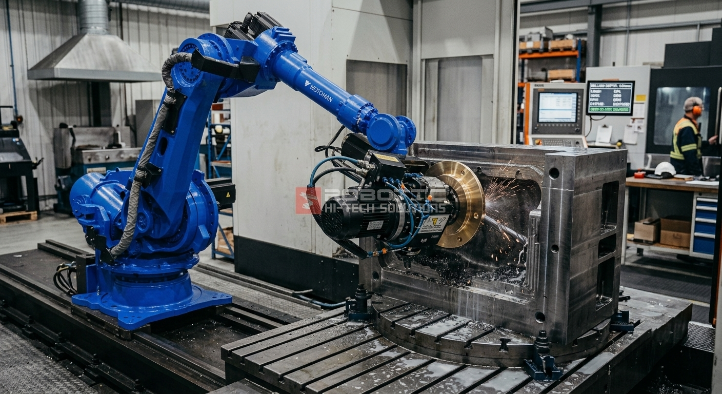

Tool stick-out robotic milling decisions directly influence vibration, tool deflection, surface finish, and dimensional accuracy. Tool stickout is the unsupported distance between the toolholder or spindle interface and the active cutting area of the tool.
Engineers often focus on tool diameter, flute geometry, coating, and cutting material when selecting a milling tool. However, even a correctly selected cutter can become unstable when it extends too far from the holder.
This issue is particularly important when a robotic milling cell must machine deep cavities, large composite molds, aluminum tooling, free-form surfaces, or areas with restricted access. In these applications, a longer tool may be necessary, but its effect on the entire machining system must be evaluated before production begins.
Why Tool Stick-Out Matters in Robotic Milling
A cutting tool behaves like a cantilevered structural element. As its unsupported length increases, its resistance to bending decreases. Therefore, the same cutting force can produce more displacement at the tool tip when a longer extension is used.
Excessive stick-out can contribute to:
- Dynamic vibration and chatter
- Tool-tip deflection
- Surface waviness
- Visible chatter marks
- Rounded edges or distorted details
- Dimensional variation
- Premature cutter wear
- Reduced process repeatability
However, tool length is not the only source of instability. Robot posture, spindle condition, toolholder quality, fixture stiffness, workpiece geometry, and cutting parameters also affect machining behavior. For that reason, tool stickout should be analyzed as part of the complete robotic milling system.
The Mechanical Effect of a Long Tool
A long tool creates a larger mechanical lever between the cutting edge and the holder. Consequently, forces acting at the cutting edge can generate greater bending moments and greater displacement.
The relationship is not simply linear. Small increases in unsupported length can produce a substantial reduction in bending stiffness. The exact effect depends on factors such as tool diameter, tool material, holder interface, and cutting geometry.
A longer tool can, therefore, become more sensitive to changes in:
- Radial cutting force
- Axial cutting force
- Tool engagement
- Material density
- Feed per tooth
- Depth of cut
- Step-over
- Robot acceleration
When the cutting force changes during each tool rotation, the extended tool may bend and recover repeatedly. If this excitation interacts with the natural frequencies of the tool, spindle, robot, workpiece, or fixture, unstable vibration may develop.
Tool Stick-Out and Robotic System Flexibility
Industrial robots provide a large working envelope and multi-axis flexibility. Nevertheless, their structural behavior differs from that of a heavy machining center or gantry system.
The effective stiffness of a robot varies according to its position and joint configuration. A compact posture near the robot base may behave differently from an extended posture near the edge of the working envelope.
In a tool stick-out robotic milling application, the extended cutter adds another flexible element to the kinematic chain. The complete chain may include:
- The robot foundation
- The robot base
- The arm and wrist axes
- The spindle mounting structure
- The spindle bearings
- The toolholder
- The cutting tool
- The workpiece and fixture
Weakness or movement in any of these elements can affect the cutting process. Therefore, increasing tool length without evaluating the rest of the system can reduce stability even when the cutter itself is technically suitable for the material.
Interaction Between Tool Length and Robot Dynamics
When robots from manufacturers such as KUKA, ABB, or FANUC are integrated into machining cells, tool extension must be evaluated together with robot payload, wrist loading, spindle mass, and dynamic motion.
A longer tool increases the distance between the cutting point and the wrist structure. This can amplify the effect of cutting forces and dynamic movement at the end of the robot.
Important engineering factors include:
- Robot wrist torque limits
- Permitted payload and center of gravity
- Spindle mass and mounting offset
- Acceleration and deceleration settings
- Robot posture during cutting
- Tool center point calibration
- Programmed path transitions
- Cutting-force direction
The tool stick-out alone does not determine whether wrist limits will be exceeded. The complete spindle, holder, and tool assembly must be considered when calculating mass, center of gravity and inertia.
Furthermore, cutting forces are process loads rather than static payload alone. A suitable integration review should therefore consider both the mechanical tool package and the forces expected during machining.
Why Deep Cavities Require Longer Tools
Deep cavity machining often requires additional reach because the spindle body, toolholder, or robot wrist cannot enter the geometry without creating a collision risk.
Common applications include:
- Composite mold cavities
- Patterns and plugs
- Large aerospace tooling
- Automotive molds
- Marine components
- Architectural forms
- Large foam and resin models
In these cases, the shortest standard tool may not provide sufficient access. Nevertheless, selecting a much longer tool than necessary can introduce avoidable flexibility.
A better tool-stick-out robotic milling strategy uses the shortest extension that can safely reach the required surface while preserving clearance around the spindle, holder, robot wrist, and workpiece.
How Tool Deflection Affects Dimensional Accuracy
Tool deflection occurs when cutting forces displace the cutting edge from its intended position. As a result, the physical cutting path may differ from the programmed robot path.
Possible consequences include:
- Insufficient material removal
- Excess material removal after tool recovery
- Wall taper
- Rounded corners
- Profile variation
- Inconsistent cavity dimensions
- Uneven finishing allowance
Deflection may also change as tool engagement changes. For example, the tool can bend more when entering a corner or encountering a larger radial engagement. Once the cutting load decreases, the tool may move back toward its unloaded position.
This behavior makes dimensional errors difficult to correct through a single static offset. The process should instead be stabilized by reducing the causes of deflection and controlling the cutting load.
How Stick-Out Influences Surface Finish
Surface finish depends on the relationship between the cutting edge, material, and programmed toolpath. When a long tool vibrates or bends, the cutting edge may not contact the surface consistently.
This can produce:
- Periodic vibration marks
- Wavy finishing patterns
- Variations between adjacent toolpaths
- Local gouging
- Uncut material
- Irregular edge quality
Free-form surfaces are especially sensitive because the tool orientation and contact point change continuously. As the robot follows the geometry, both the cutting-force direction and robot posture may vary.
For this reason, surface quality should not be evaluated only on a short, straight test cut. Test passes should represent the actual orientations, depths, and tool engagement expected in production.
Seven Strategies for Managing Tool Stick-Out
1. Use the shortest safe extension
Tool extension should be minimized for each machining operation. The tool must still provide adequate clearance, but unnecessary length should be avoided.
Where practical, separate tools can be assigned to shallow and deep areas instead of using one long tool for the entire component.
2. Increase tool diameter when geometry allows
A larger tool diameter can improve bending stiffness. However, diameter selection must remain compatible with the required features, corner radii, spindle power, toolholder, and material.
Increasing diameter is therefore an engineering option, not a universal solution.
3. Use a rigid and balanced toolholder
The toolholder must provide sufficient clamping force, low runout, and reliable rotational balance. Contamination, wear, or incorrect assembly can reduce the quality of the spindle-to-tool connection.
For high-speed machining, the complete rotating assembly should be suitable for the intended spindle speed. The tool, holder, collet, and retention system must be evaluated as one assembly.
4. Reduce aggressive tool engagement
When a long tool is unavoidable, cutting parameters may need to be adapted. Potential adjustments include reducing radial engagement, axial depth, feed, or step-over.
However, reducing spindle speed alone is not always the correct response. Stability depends on the complete combination of spindle speed, tooth passing frequency, tool geometry, material, and structural dynamics.
5. Select low-force cutting geometry
Sharp cutting edges and suitable rake geometry can reduce cutting resistance in certain materials. Tool selection should reflect the specific workpiece material, spindle, and machining operation.
A tool designed for aluminum may not be appropriate for composites, foam, resin, or other materials. Manufacturer recommendations should be reviewed for the actual application.
6. Improve robot posture and motion planning
The toolpath should avoid unnecessarily weak robot configurations whenever possible. Smooth orientation changes and controlled acceleration can reduce abrupt dynamic loading.
Offline programming and simulation can help engineers review robot reach, wrist orientation, singularities, joint motion, and collision clearance before machining begins.
7. Separate roughing and finishing strategies
Roughing and finishing create different process demands. Roughing usually removes more material and produces higher cutting loads. Finishing uses lighter engagement but requires greater surface and dimensional consistency.
A stable process may use a more rigid, shorter tool for accessible roughing areas and a longer tool only where cavity depth makes it necessary.
Should Spindle Speed Be Reduced?
Reducing spindle speed may improve stability in some situations, but it can worsen vibration in others. Chatter is related to the dynamic interaction among spindle speed, tooth engagement, and structural response.
Therefore, the appropriate response may involve changing:
- Spindle speed
- Feed per tooth
- Number of engaged cutting edges
- Radial engagement
- Axial depth
- Toolpath direction
- Robot posture
Parameter changes should be validated through controlled test cuts. Randomly reducing every parameter can increase cycle time without eliminating the underlying instability.
Tool Stick-Out and Fixture Stability
The tool and workpiece interact during machining. A rigid tool cannot fully compensate for a flexible fixture, and a rigid fixture cannot eliminate instability caused by an excessively flexible tool.
When a long cutter is used, the tool stick-out robotic milling assessment should also include:
- Workpiece support distribution
- Clamp position
- Fixture deflection
- Material porosity
- Vacuum-holding performance
- Unsupported spans
- Cutting-force direction
For large molds and thin-wall parts, local workpiece movement may resemble tool deflection. Engineers should distinguish between these sources before changing the tool or machining parameters.
How to Validate a Long-Tool Application
A long-tool setup should be validated under representative operating conditions. The test should reproduce the material, robot posture, spindle speed, tool engagement, and cavity depth expected during production.
A structured validation process may include:
- Confirm that the tool and holder are correctly assembled.
- Measuring tool runout at an appropriate location.
- Checking the complete tool assembly against the spindle requirements.
- Confirming robot payload and center-of-gravity data.
- Reviewing collision clearance throughout the toolpath.
- Running conservative test passes.
- Monitoring sound, vibration, and surface appearance.
- Measuring critical dimensions after machining.
- Adjusting the toolpath or cutting parameters systematically.
- Documenting the validated setup for future production.
For demanding applications, accelerometers, spindle monitoring, dimensional metrology, or modal testing may provide additional information. The appropriate level of validation depends on the tolerance, component value, and production risk.
Technical Checklist for Tool Stick-Out Robotic Milling
- Is the tool extension minimized for each operation?
- Is the tool diameter appropriate for the required reach?
- Is the holder suitable for the planned spindle speed?
- Has the tool runout been checked?
- Are the robot payload and center of gravity configured correctly?
- Have wrist torque and inertia limits been evaluated?
- Does the toolpath avoid weak robot postures where practical?
- Are acceleration and path transitions controlled?
- Are radial engagement and cutting depth appropriate?
- Is the workpiece fixture rigid under representative loads?
- Has vibration been evaluated during test passes?
- Have critical dimensions and surface finish been inspected?
- Has the validated setup been documented?
Safety During Tool Setup and Testing
Long tools can change the robot’s reach, collision envelope, and clearance requirements. These changes should be considered in the cell risk assessment and during program validation.
Setup, testing, and adjustment activities require particular care because personnel may need temporary access near the robotic system. The Occupational Safety and Health Administration’s robotics guidance provides information about hazards associated with industrial robot systems and non-routine operations.
Tool setup should follow the cell’s approved safety procedures. Guarding, interlocks, operating modes, access controls, and energy-isolation requirements must not be bypassed during testing or adjustment.
Additional Technical Guidance on Milling Vibration
For more information about the relationship between tool overhang, holding systems, and milling vibration, consult Sandvik Coromant’s technical guidance on milling vibration .
The guidance reinforces an important engineering principle: vibration can originate from the cutting tool, toolholder, machine structure, workpiece, or fixture. Therefore, troubleshooting should evaluate the complete machining system.
Frequently Asked Questions
Are long tools more problematic in robotic milling than in CNC machining?
They can be more sensitive because robotic systems and conventional CNC machines have different structural characteristics. However, actual stability depends on robot posture, tool diameter, spindle, holder, cutting parameters, workpiece, and fixture.
Does reducing spindle speed always improve stability?
No. A speed reduction may improve stability in one operating range but increase vibration in another. Spindle speed should be adjusted together with feed, engagement, tool geometry, and system dynamics.
Is tool stick-out important only during finishing?
No. It affects both roughing and finishing. Roughing may generate higher cutting forces, while finishing is usually more sensitive to small dimensional and surface deviations.
Can a larger tool diameter compensate for additional length?
A larger diameter can increase bending stiffness, but it must remain compatible with the geometry, corner radii, spindle capacity, and toolholder. It may not be suitable for every cavity or detail.
Should one long tool be used for the entire workpiece?
Not necessarily. Using shorter tools for accessible areas and a longer tool only for deep sections can improve stability and reduce unnecessary vibration.
Can a tool runout increase vibration?
Yes. Excessive runout can create uneven tooth loading, inconsistent material removal, and premature tool wear. The holder, collet, tool, and spindle interface should be inspected.
How does robot posture affect a long-tool setup?
Robot stiffness and joint loading change across the working envelope. An extended or unfavorable posture may amplify displacement and vibration at the cutting point.
Can tool deflection be corrected with a programmed offset?
A static offset may compensate for a consistent error, but cutting deflection often changes with engagement and force direction. Stabilizing the process is generally more reliable than relying only on compensation.
When should a tool-stick-out robotic milling setup be revalidated?
The setup should be reviewed when the tool, holder, material, robot posture, spindle speed, cutting parameters, fixture, or workpiece geometry changes. It should also be reassessed when unexpected vibration or dimensional variation appears.
Conclusion
Tool stick-out robotic milling performance depends on much more than selecting a cutter that can physically reach the surface. Tool extension influences bending stiffness, vibration, robot loading, surface quality, and dimensional consistency.
Long tools can be used successfully when the complete process is engineered around them. The tool, holder, spindle, robot posture, cutting parameters, fixture, and workpiece must function as a coordinated system.
By using the shortest practical tool, controlling engagement, validating the holder assembly, and testing representative machining conditions, manufacturers can preserve access without unnecessarily sacrificing stability.
Plan a More Stable Robotic Milling Process
Robotic Hi-Tech Solutions designs and integrates large-format robotic milling cells for complex molds, tooling, and industrial components. Each project considers the robot, spindle, tooling, workpiece support, toolpath, and required machining access.
For applications involving deep cavities, extended reach, or challenging free-form surfaces, our engineering team evaluates tool configuration and system dynamics as part of the complete integration process.
Contact Robotic Hi-Tech Solutions to discuss the technical requirements of your robotic milling application. “`