English
 Italiano
 Українська
 Русский
 Español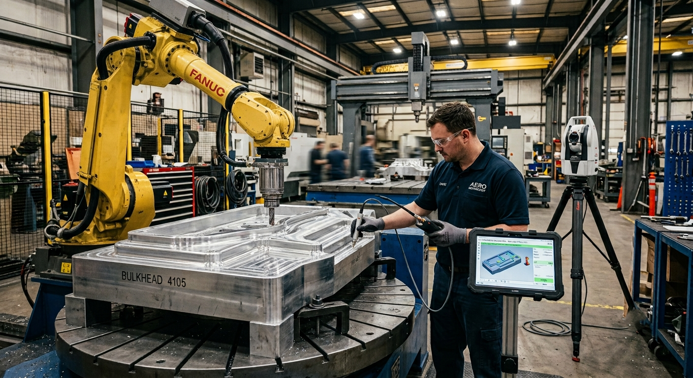

Robotic milling tolerance validation determines whether a machined component complies with the geometric requirements specified on its engineering drawing. These requirements may include flatness, parallelism, perpendicularity, position, profile, circularity, or concentricity, depending on the part and the applicable drawing standard.
A robot’s published repeatability value cannot confirm that the finished component meets those requirements. Repeatability describes the ability to return to similar commanded positions under defined conditions. In contrast, part conformity depends on the complete machining and measurement process.
Therefore, engineers must evaluate the robot, spindle, cutting tool, fixture, workpiece, calibration method, environmental conditions, and inspection system as one coordinated process. Only measured results can demonstrate whether the required geometric tolerance has been achieved.
What Does Geometric Tolerance Validation Mean?
Geometric tolerance validation is the process of measuring a finished or partially finished feature and comparing the result with the tolerance specified on the drawing or digital product definition.
The inspection must identify:
- The geometric characteristic being controlled
- The nominal geometry or basic dimensions
- The tolerance value and tolerance zone
- The applicable datum reference frame
- The measurement method
- The environmental and setup conditions
- The measurement uncertainty
- The acceptance criteria
For example, planarity can be evaluated without a datum because flatness controls an individual surface. Parallelism, however, normally controls the orientation of a feature relative to a specified datum. Position and profile controls may also depend on a complete datum reference frame.
For this reason, robotic milling tolerance validation must follow the engineering definition of the feature rather than relying on a general scan or a visual comparison with the CAD model.
Why Robot Repeatability Is Not Enough
Industrial robot specifications frequently include pose repeatability. This value is useful, but it does not represent the dimensional accuracy of a milled component.
During machining, the tool position can be influenced by:
- Robot kinematic-model errors
- Joint compliance and backlash
- Robot posture
- Spindle and tool mass
- Cutting-force magnitude and direction
- Tool deflection and wear
- Fixture deformation
- Workpiece movement
- Thermal variation
- External-axis alignment
- Toolpath interpolation
A robot may repeatedly follow the same path while that path remains offset from its nominal location. Likewise, a repeatable process can produce a consistent geometric error if the tool center point, work-object frame, or kinematic model is incorrect.
Consequently, repeatability supports process consistency, but it does not independently prove flatness, parallelism, position, or any other geometric requirement.
The ISO 9283 industrial robot performance standard provides criteria and test methods for evaluating robot performance characteristics. However, validating a finished workpiece still requires part-specific dimensional inspection.
Seven Critical Steps in Robotic Milling Tolerance Validation
1. Define the Required Characteristic and Datum Structure
The first step is to identify exactly what the drawing requires. Terms such as “accuracy,” “precision,” and “concentricity” should not be used as interchangeable descriptions.
Engineers should confirm:
- Which surface, axis, center plane, or feature is controlled
- Whether the control applies to form, orientation, location, or profile
- Which datums establish the reference system
- Whether material-condition modifiers apply
- Whether the tolerance applies to the complete surface or a defined area
- Which drawing and dimensioning standard governs interpretation
Without this information, the inspection team may measure the wrong characteristic or align the data incorrectly.
For example, comparing a scanned surface directly with a best-fit CAD alignment may hide a datum-related orientation error. A best-fit comparison can be useful for process analysis, but it may not be the correct method for demonstrating drawing compliance.
2. Validate the Robotic Machining System Before Cutting
Before manufacturing the qualification part, the integrator should verify the principal geometric relationships within the cell.
Pre-process validation commonly includes:
- Robot mastering or reference verification
- Kinematic calibration when required
- Tool center point calibration
- Spindle-axis verification
- Work-object or fixture-frame calibration
- External-axis calibration
- Track straightness and alignment checks
- Positioner-axis calibration
- Fixture location and rigidity verification
Tool center point errors can affect both the location and orientation of the cutter, particularly when the robot changes orientation during a complex path. Similarly, a work-object error can shift the entire programmed operation relative to the physical component.
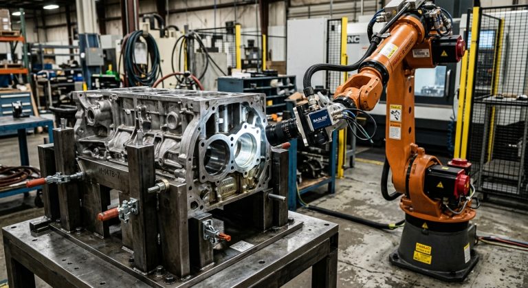
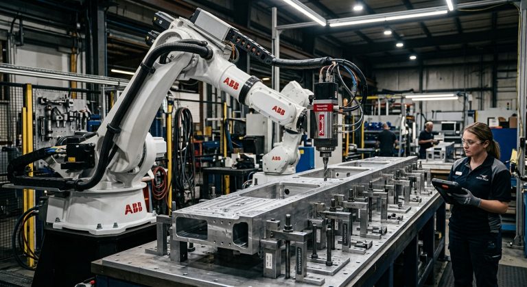
ABB’s official Machining Software, for example, includes calibration functions for machining tools, cutters, and work objects. Such functions support cell setup, but the resulting workpiece must still undergo independent dimensional verification.
3. Qualify the Fixture and Workpiece Setup
A correctly calibrated robot cannot compensate for an unstable workpiece. Fixturing must preserve the intended datum relationships while resisting gravity, clamping forces, and machining loads.
The qualification process should assess:
- Fixture base stability
- Support-point location
- Clamp-force distribution
- Workpiece deformation during clamping
- Accessibility of datum features
- Repeatability between loading cycles
- Thermal expansion of the fixture and component
Thin composite panels, foam patterns, polymer blocks, and large aluminum structures may deform differently under their own weight or under clamping pressure. Therefore, the inspection condition must also be defined.
A part measured while restrained in its production fixture may produce a different result after it is released. The inspection plan should state whether conformity applies in the restrained, supported, or free-state condition.
4. Control the Machining Process
Robotic milling tolerance validation begins before the inspection stage because uncontrolled cutting conditions can produce geometric errors that measurement alone cannot correct.
Important process variables include:
- Robot posture and arm extension
- Tool orientation
- Radial and axial tool engagement
- Feed rate and spindle speed
- Material-removal sequence
- Tool length and diameter
- Tool wear
- Roughing allowance
- Finishing-pass direction
- Thermal stabilization
Roughing and finishing should normally be treated as different process stages. Roughing removes the majority of the material and may release internal stresses or alter the thermal state of the part. A finishing allowance preserves material for the final controlled pass.
Depending on the component, the process may benefit from a stabilization period, intermediate measurement, or semi-finishing pass before final machining.
5. Use In-Process Measurement Where It Adds Value
In-process probing can verify the relationship between the workpiece and the robot program before or during machining. A touch probe, laser sensor, or other measuring device may locate datums, identify setup offsets, or inspect selected reference features.
In-process measurement can support:
- Workpiece alignment
- Fixture-offset correction
- Stock-condition verification
- Reference-feature measurement
- Tool-length checks
- Intermediate process decisions
- Controlled re-machining
However, a probe mounted on the same robot that performs the machining is not automatically an independent inspection system. Robot-position uncertainty, probe calibration, and measurement strategy still affect the result.
For that reason, integrated probing is particularly valuable for process setup and compensation, while final acceptance of demanding tolerances may require an independent metrology system.
6. Select the Correct Post-Process Inspection Method
No single instrument is appropriate for every geometric characteristic, component size and tolerance level.
Common inspection technologies include:
Coordinate measuring machines
A coordinate measuring machine can evaluate a wide range of dimensional and geometric characteristics under controlled conditions. It may be suitable for components that fit within the machine volume and can be supported appropriately.
Large components may require a bridge, gantry, or horizontal-arm CMM. Accessibility, environmental control, and part transport must be considered.
Portable measuring arms
Portable articulated arms can measure large components directly on the production floor. Depending on the system, they may use tactile probes, laser scanners, or both.
They provide flexibility, but their achievable uncertainty depends on arm size, operator technique, environmental conditions, and measurement strategy.
Laser trackers
Laser trackers can measure three-dimensional points across large working volumes. They are often used for alignment, machine calibration, fixture inspection, and dimensional verification of large structures.
They can support large-format robotic milling tolerance validation, but the inspection plan must establish whether the tracker’s uncertainty and point-access strategy are suitable for the specific tolerance.
Structured-light and laser scanning systems
Optical scanning can capture dense surface data for profile analysis, surface comparison, and deviation mapping. It is particularly useful for molds, free-form surfaces, and composite tooling.
Nevertheless, scan density does not automatically equal measurement accuracy. Calibration, surface reflectivity, registration method, datum alignment, and system uncertainty all influence the result.
Precision levels, indicators, and straightedges
Traditional metrology tools may provide efficient verification for selected surfaces and simpler geometric requirements. For example, a precision indicator swept across a qualified reference can support flatness or parallelism analysis.
The method must produce sufficient data to evaluate the complete tolerance zone rather than a few unrepresentative points.
7. Account for Measurement Uncertainty
A measurement result is not complete without an understanding of its uncertainty. If the measurement system’s uncertainty is too large in relation to the specified tolerance, the inspection may not provide a defensible acceptance decision.
The uncertainty budget may include contributions from:
- Instrument calibration
- Probe or scanner performance
- Operator technique
- Part temperature
- Air temperature and gradients
- Vibration
- Surface condition
- Alignment and registration
- Sampling density
- Measurement software
The required relationship between uncertainty and tolerance depends on the organization’s quality system, customer requirements, and applicable standards. Therefore, the inspection plan should define the decision rule before measurements begin.
How Is Flatness Validated?
Flatness controls how much an individual surface can deviate between two parallel planes. It does not require a datum reference.
To evaluate flatness, the inspection system collects points across the relevant surface. The analysis then determines the minimum separation between two parallel planes that contain the measured surface data, according to the selected evaluation method and standard.
Important considerations include:
- Coverage of the complete controlled area
- Sufficient point density
- Exclusion or inclusion of surface texture
- Filtering rules
- Support and restraint conditions
- Temperature during measurement
A straightedge can identify local gaps or gross deviations, but it may not provide enough information for a rigorous assessment of a complex or very large surface. CMMs, portable systems, and optical scanners can provide more complete surface data when properly applied.
How Is Parallelism Validated?
Parallelism controls the orientation of a feature relative to a datum. Therefore, the datum must first be established using the method defined by the drawing standard and inspection plan.
For surface parallelism, the measured surface must remain within two parallel planes oriented relative to the datum. For axis parallelism, the tolerance zone and evaluation method differ.
A common mistake is to compare two independently fitted planes and report only their angular difference. That result may support process analysis, but it does not always represent the complete parallelism requirement because the tolerance zone can also constrain the feature’s total variation.
Reliable robotic milling tolerance validation should reconstruct the datum reference correctly before evaluating the controlled surface or axis.
How are circularity, runout, and concentricity validated?
Circularity, runout, coaxiality, and concentricity describe different geometric conditions. The drawing should be reviewed carefully before choosing the measurement strategy.
Circularity evaluates individual circular elements without a datum. Runout evaluates surface variation as the part rotates around a datum axis. Concentricity, where specified under the applicable drawing system, requires an analysis of derived median points relative to a datum axis and can be more demanding to inspect.
Potential inspection methods include:
- CMM probing
- Roundness-measuring equipment
- Rotary-table inspection
- Precision indicators for appropriate runout checks
- Portable metrology for sufficiently large features
A small number of diameter measurements is not enough to establish circularity or concentricity. The measurement strategy must capture the feature geometry required by the tolerance definition.
How External Linear Axes Affect Tolerance Validation
A track-mounted robot can extend the machining envelope, but the external axis becomes part of the overall error chain.
Validation should consider:
- Track straightness
- Carriage positioning performance
- Track-to-robot calibration
- Foundation alignment
- Structural deformation
- Servo synchronization
- Cable and hose forces
- Variation across the complete travel range
Testing only one carriage position is not sufficient when the production toolpath uses several meters of travel. Qualification measurements should represent the positions, directions, and postures used during the actual process.
Can Robotic Milling Achieve CNC-Level Tolerances?
The phrase “CNC-level tolerance” is too broad to support a technical acceptance decision. CNC machines vary substantially in size, rigidity, configuration, and performance. Robotic cells also vary according to robot model, calibration, spindle, tooling, foundation, and integration quality.
Robotic milling can satisfy defined tolerances in suitable applications. However, the requirement should be expressed as a measurable value on a specific component, not as a general comparison with CNC machining.
Robotic systems are often attractive for:
- Large working envelopes
- Complex tool orientations
- Composite trimming
- Foam and polymer machining
- Patterns and molds
- Large components with moderate cutting forces
Conventional machine tools may remain preferable when the process requires very high rigidity, heavy material removal, extremely tight tolerances, or highly controlled thermal behavior.
The correct decision depends on the workpiece, material, tolerance, productivity target, and total production architecture.
Robotic Milling Tolerance Validation Checklist
- Is the required geometric characteristic clearly defined?
- Have the applicable datums been identified?
- Is the drawing standard confirmed?
- Has robot mastering or calibration been verified?
- Is the tool center point calibrated?
- Is the spindle axis verified?
- Is the work object or fixture frame calibrated?
- Has fixture deformation been evaluated?
- Is the inspection condition defined as a restrained or a free state?
- Are cutting forces and robot postures controlled?
- Is sufficient finishing allowance available?
- Are thermal stabilization requirements documented?
- Is in-process probing used where it provides measurable value?
- Is the final inspection method independent when required?
- Can the instrument measure the complete feature?
- Is measurement uncertainty suitable for the tolerance?
- Is the datum alignment reproduced correctly in the software?
- Are acceptance criteria and decision rules documented?
- Are the results traceable to the inspected part and revision?
FAQ’s
Can robotic milling achieve demanding flatness requirements?
Yes, in suitable applications. The achievable result depends on the part size, material, robot posture, fixture, cutting strategy, thermal conditions, and inspection method. The requirement must be demonstrated through measurement.
Does robot repeatability guarantee dimensional accuracy?
No. Repeatability indicates how consistently the robot returns to commanded positions under specified conditions. It does not independently account for calibration errors, deflection, tooling, fixturing, or process forces.
Is integrated probing necessary?
Not for every application. However, it can improve setup verification, workpiece localization, and process control. Tight tolerances may still require independent final inspection.
Can a 3D scan certify flatness?
Potentially, provided that the scanner, calibration, surface preparation, point registration, analysis method, and measurement uncertainty are suitable for the required tolerance.
Is a laser tracker suitable for large-format inspection?
Laser trackers are widely used for large-volume measurement, alignment, and calibration. Their suitability for a particular feature depends on access, measurement strategy, and uncertainty relative to the tolerance.
Should inspection use a best-fit CAD alignment?
Not automatically. Best-fit alignment is useful for visualization and process analysis, but drawing compliance may require alignment to specified datums rather than a global best fit.
Does an external linear axis reduce accuracy?
Not necessarily. However, the track adds another mechanical and calibrated axis. Its straightness, foundation, positioning performance, and synchronization must be included in the validation plan.
How often should the robotic cell be recalibrated?
The interval depends on process risk, production volume, collisions, maintenance activity, environmental conditions, and quality requirements. Verification should also follow events that may alter the robot, tool, fixture, or external-axis geometry.
Can inspection data be used to correct the toolpath?
Yes. Measured deviations may support controlled offset changes, local compensation, or a revised finishing path. Corrections should be validated because an apparent deviation may also result from measurement alignment or fixture movement.
Who should approve the measurement strategy?
The responsible engineering, quality, and metrology teams should agree on the characteristic definition, datum setup, instrument, sampling strategy, uncertainty, and acceptance rule before production validation begins.
Conclusion
Robotic milling tolerance validation is a structured engineering and metrology process. It does not rely solely on robot repeatability or nominal equipment specifications.
Reliable validation begins with the drawing and its datum structure. It then includes system calibration, fixture qualification, controlled machining, appropriate measurement technology, and an uncertainty-based acceptance decision.
When these elements are planned together, robotic milling cells can produce and verify large-format components against clearly defined geometric requirements. The result is not an assumed level of precision but documented evidence of process capability and part conformity.
Validate Your Robotic Milling Process
Robotic Hi-Tech Solutions designs and integrates large-format robotic milling cells with calibration, probing, and metrology strategies selected for the application’s actual geometric requirements.
If your component requires controlled flatness, parallelism, position, profile, or dimensional accuracy, our engineering team can evaluate the complete process—from robot and spindle configuration to fixturing, toolpath development, and final inspection.