English
 Italiano
 Українська
 Русский
 Español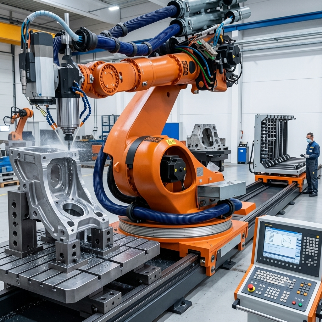

Linear axis robotic milling becomes necessary when a fixed six-axis robot cannot machine the required area while maintaining suitable posture, accessibility, and process stability.
A robot may technically reach a large mold, panel, or composite structure at maximum extension. However, that position may place the wrist close to its limits, reduce directional stiffness, restrict tool orientation, or create inefficient movements between machining zones.
Mounting the robot on a servo-controlled linear track can extend the working envelope and allow the arm to remain closer to a more favorable configuration. Nevertheless, the track also introduces another controlled axis, additional calibration requirements, and a larger mechanical foundation.
Therefore, a linear axis should be selected only after evaluating the complete machining process, including the part geometry, toolpaths, cutting forces, tolerances, cell layout, and production strategy.
What Is an External Linear Axis in Robotic Milling?
An external linear axis is a motorized track that moves the robot base along a straight path. It is commonly described as a seventh axis because it operates in addition to the six articulated axes of the industrial robot.
However, the system is not the same as a seven-axis articulated robot. The first six axes still control the robot arm, while the external axis translates the complete robot along the track.
Depending on the controller and integration strategy, the track may operate in one of two ways:
- Indexed movement: The robot stops machining, travels to another track position, and then resumes the operation.
- Synchronized movement: The robot and track move together as part of the programmed toolpath.
Synchronized motion can support long or continuous machining paths. However, it requires accurate kinematic configuration, calibration, and motion coordination.
Official KUKA linear-unit documentation explains that the linear unit can be integrated as a mathematically coupled axis in the robot controller. Similarly, the ABB IRT 710 Track Motion platform is designed to extend a robot’s working area as an external seventh axis.
Seven Criteria for Selecting a Linear Track
1. The workpiece exceeds the practical robot envelope
The clearest reason to consider external linear-axis robotic milling is that the part exceeds the practical working envelope of a stationary robot.
The word “practical” is important. The maximum reach stated on a robot data sheet represents a geometric limit. It does not guarantee that the robot can maintain the required spindle orientation, avoid singularities, or produce a stable machining path at every point within that envelope.
A linear track may be justified when the robot must machine:
- Long composite molds
- Large aerospace or transportation panels
- Oversized patterns and tooling
- Architectural free-form components
- Boat, rail or automotive structures
- Long plastic, foam, wood or aluminum parts
Before selecting the track, engineers should simulate the complete toolpath rather than comparing only the workpiece dimensions with the robot’s nominal reach.
2. The robot operates too frequently near maximum extension
A robot that can reach the entire part may still spend too much of the cycle in an unfavorable posture. Long arm extension can increase the mechanical leverage created by the spindle and cutting forces.
The resulting process may become more sensitive to:
- Tool engagement changes
- Spindle and tool mass
- Cutting-force direction
- Robot-axis compliance
- Acceleration and deceleration
- Sudden changes in tool orientation
Moving the robot base closer to each machining zone can reduce the need for extreme arm extension. Consequently, the robot may operate in a more favorable portion of its envelope.
Nevertheless, the track does not make the robot inherently rigid. The complete structure still includes the robot, carriage, track, pedestal, anchors and foundation. Each component must be evaluated under the expected process loads.
3. The process requires long continuous toolpaths
Some large-format applications include paths that extend across several meters. Dividing these paths into separate machining zones may create unnecessary retractions, transitions or surface discontinuities.
In these situations, synchronized external linear axis robotic milling can allow the robot and track to move together while the cutter follows the programmed geometry.
This approach may be useful for:
- Trimming long composite edges
- Machining elongated molds
- Processing continuous architectural surfaces
- Drilling distributed features along large panels
- Milling long profiles or structural components
However, synchronized motion is not automatically better than indexed movement. If the process can be divided into stable machining zones without affecting quality, indexed track positions may simplify programming and validation.
4. Repositioning the workpiece is inefficient or risky
Without a track, manufacturers may extend the machining area by repositioning the component. This strategy can be practical for small batches or simple fixtures, but it also introduces additional setup operations.
Every repositioning step may require:
- Stopping the machining program
- Releasing and moving the workpiece
- Repeating alignment procedures
- Verifying reference points
- Managing overlap between machining zones
- Confirming that the fixture remains stable
For large, heavy or delicate components, repositioning may require cranes, forklifts or special handling equipment. It can also increase the risk of alignment errors or damage.
A track-mounted robot can move between different areas of a stationary workpiece. Therefore, it may reduce handling operations and simplify the fixture concept.
Still, a moving robot is not always the most effective architecture. In some applications, placing the workpiece on a servo-controlled positioner provides better access or allows gravity and chip evacuation to work more favorably.
5. Tool orientation cannot be maintained from one robot position
Large-format machining is not only about reaching Cartesian coordinates. The cutter must also approach the surface at the required orientation.
A stationary robot may reach a point but fail to maintain the tool angle needed for:
- Correct cutter engagement
- Collision-free spindle positioning
- Consistent surface-normal machining
- Trimming from the correct side
- Drilling perpendicular to the surface
Moving the robot base can improve access by changing the relationship between the robot, workpiece and toolpath. This additional degree of freedom may help the offline programming system find more suitable robot configurations.
Nevertheless, the extra freedom also increases the number of possible solutions. Motion planning must control how the track is used instead of allowing unnecessary or unstable axis movement.
6. One robot must serve several work zones
A linear track can allow one robot to serve multiple fixtures, stations, or sections of a large production cell. In this configuration, the track supports more than machining reach; it also becomes part of the production-flow strategy.
For example, one robot may travel between:
- Two alternating machining fixtures
- A machining station and a tool-service area
- Several workpiece positions
- Separate loading and processing zones
- Multiple parts arranged along the track
This architecture may improve equipment utilization. While an operator unloads one station, the robot may machine a component at another station, provided that the safety concept permits the planned operating mode.
However, engineers must compare this solution with alternatives such as additional robots, rotating fixtures, or movable workpiece systems. A longer track does not automatically provide the lowest total production cost.
7. Future product dimensions require a scalable cell
Manufacturers sometimes select external linear axis robotic milling because future components may be longer than the parts currently in production.
A modular track can support cell expansion, but future flexibility should be defined carefully. Adding unused travel length increases the required floor area, guarding, cable management and foundation work.
The engineering team should identify realistic future requirements, including:
- Maximum expected component length
- Potential additional fixtures
- Required track travel
- Robot and spindle payload
- Changes in tooling and process forces
- Expected production volume
A scalable design is valuable when it responds to a documented production plan. It is less valuable when it adds complexity without a defined use case.
Does a Linear Axis Improve Robotic Milling Accuracy?
An external axis can help the robot avoid unfavorable postures, but it should not be presented as a direct accuracy upgrade.
The final machining result depends on the complete system, including:
- Robot path accuracy and repeatability
- Track positioning performance
- Track straightness and alignment
- Carriage rigidity
- Foundation stability
- Robot-to-track calibration
- Tool center point calibration
- Work-object calibration
- Spindle and tool deflection
- Cutting parameters and material behavior
If the track is poorly aligned or calibrated, it can introduce errors that vary with carriage position. Therefore, validation must cover the complete travel range rather than only one reference position.
The track may improve process consistency when it keeps the arm away from extreme extension. Yet any improvement must be demonstrated through simulation, calibration trials and machining tests.
Calibration Requirements for a Seven-Axis Milling Cell
Accurate calibration is essential in external linear-axis robotic milling. The controller must understand the geometric relationship between the robot base, track, workpiece, and machining tool.
The validation process commonly includes:
- Mastering or referencing the track axis
- Defining the track coordinate system
- Calibrating the robot base relative to the track
- Calibrating the spindle tool center point
- Defining the work-object coordinate system
- Checking track straightness and installation alignment
- Verifying accuracy at several carriage positions
- Testing coordinated motion under realistic conditions
Calibration should also be reviewed after mechanical adjustments, collisions, foundation movement, or replacement of critical components.
For long tracks, small angular or alignment errors can become more significant as the robot moves farther from the calibration reference. For this reason, acceptance testing should include representative positions across the complete operating range.
Track Rigidity, Foundation, and Installation
The track is part of the machining structure. Its installation cannot be treated like a simple material-handling accessory when the robot will generate dynamic cutting loads.
Engineers should evaluate:
- Track-beam stiffness
- Carriage bearing arrangement
- Anchoring method
- Foundation flatness and strength
- Levelling and alignment tolerances
- Dynamic loads during acceleration
- Machining-force direction
- Vibration transmission
- Protection from chips and dust
- Lubrication and maintenance access
A track designed for handling applications should not automatically be assumed suitable for demanding milling. The selected system must be evaluated against the robot mass, spindle package, process dynamics, and required machining performance.
Programming and Simulation Considerations
A seven-axis system offers a larger solution space than a fixed robot. It also creates more opportunities for axis limits, singularities, and unexpected posture changes.
Offline programming and digital simulation should evaluate:
- The complete toolpath and track motion
- Robot joint limits
- Track travel limits
- Singularity risks
- Spindle and cable clearance
- Collisions with fixtures and guarding
- Carriage acceleration and deceleration
- Transition between machining zones
- Maintenance and tool-change positions
- Recovery after an interrupted cycle
Simulation can reduce integration risk, but physical commissioning remains necessary. The final system should be tested at a controlled speed before executing production paths under full machining conditions.
When a Linear Track May Not Be Necessary
An external linear axis may add more cost and complexity than value when:
- The complete toolpath fits comfortably inside the robot’s practical envelope.
- The robot maintains a favorable posture throughout the process.
- The part can be rotated efficiently on a positioner.
- Workpiece repositioning is simple and infrequent.
- Production volume does not justify additional automation.
- A larger-reach robot can perform the process without excessive extension.
- The required accuracy is better served by another machine architecture.
In these cases, a fixed robot cell may provide a lower investment cost, simpler calibration, and easier maintenance.
The comparison should consider total system performance rather than choosing the architecture with the greatest nominal reach.
External Linear Axis Robotic Milling Checklist
- Does the complete toolpath exceed the robot’s practical working envelope?
- Does the robot operate close to maximum extension for a significant part of the cycle?
- Can the required tool orientations be achieved from a fixed base?
- Are long continuous machining paths necessary?
- Would workpiece repositioning create excessive downtime or alignment risk?
- Could a rotary positioner provide a simpler solution?
- Has the full process been evaluated in an offline simulation?
- Is synchronized movement required, or would indexed positioning be sufficient?
- Is the track rated for the robot and spindle package?
- Has track rigidity been evaluated for the expected process loads?
- Is the foundation suitable for the complete moving structure?
- Are calibration procedures defined for the robot, track, tool, and workpiece?
- Will accuracy be verified across the complete track of travel?
- Are cables, hoses, and extraction systems designed for the moving carriage?
- Can chips and dust be kept away from the track components?
- Has safe access for maintenance been included in the cell layout?
Frequently Asked Questions
Does a linear axis automatically improve milling accuracy?
No. It may help the robot maintain a more favorable posture, but it also introduces another mechanical and controlled axis. Accuracy depends on track quality, installation, calibration, and the performance of the complete machining system.
Is a robot on a linear track a seven-axis robot?
It is commonly called a seven-axis system because the track adds one controlled axis to the robot’s six axes. However, the seventh axis translates the robot base rather than adding another articulated joint to the arm.
Can the robot and track move simultaneously?
Yes, when the controller, track, and software support coordinated external-axis motion. The integration must define the correct kinematic model and validate synchronized movement.
Does a linear track reduce cycle time?
It can reduce workpiece repositioning and allow the robot to move directly between work zones. Nevertheless, tracking travel and acceleration also consumes time. The effect should be measured through a cycle simulation.
Can a track-mounted robot machine one long continuous surface?
Potentially, yes. Coordinated movement can extend the continuous path beyond the reach of a stationary robot. Surface quality still depends on calibration, path planning, track dynamics, tool engagement, and process stability.
Is a longer-reach robot better than adding a track?
Not always. A longer-reach robot may simplify the cell, while a track may provide better access to several zones. The correct choice depends on posture, payload, floor space, process forces, and future production needs.
Can an external linear axis be added to an existing milling cell?
In some cases, yes. However, engineers must assess controller compatibility, robot mounting, cable routing, guarding, foundation requirements, calibration, and changes to the existing programs.
Should the robot or the workpiece move?
The answer depends on component size, mass, geometry, and required access. Moving the robot may suit long stationary parts, while rotating or translating the workpiece may provide better orientation for other applications.
Conclusion
External linear-axis robotic milling is justified when a fixed robot cannot complete the required machining process with acceptable reach, posture, accessibility, or production efficiency.
A track can extend the working envelope, reduce workpiece repositioning, and support long coordinated paths. However, it also adds mechanical interfaces, calibration procedures, programming complexity, and foundation requirements.
For that reason, engineers should evaluate the complete toolpath, not only the dimensions of the part. When the track, robot, spindle, software, and foundation are designed as one coordinated machining system, the additional axis can turn a limited fixed cell into a scalable, large-format production platform.
Evaluate Your Large-Format Milling Application
Robotic Hi-Tech Solutions designs and integrates large-format robotic milling cells with fixed robots, servo-controlled positioners, and synchronized linear axes.
If your process involves oversized components, long continuous toolpaths, or restricted robot postures, our engineering team can evaluate whether a seven-axis configuration provides a measurable technical advantage over a fixed robotic cell.