English
 Italiano
 Українська
 Русский
 Español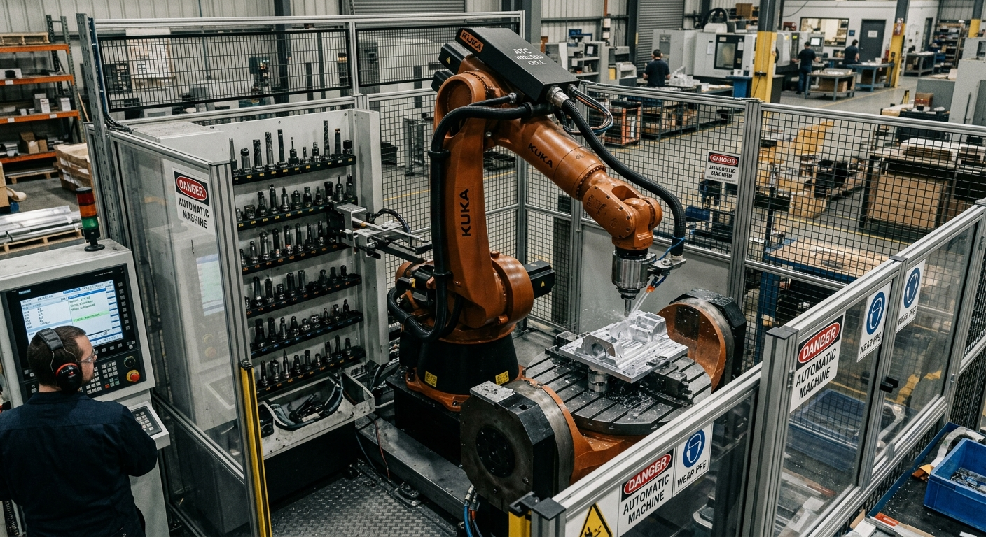

ATC robotic milling allows a robot to change cutting tools automatically during a machining program. As a result, the cell can complete roughing, semi-finishing, finishing, and trimming operations without requiring an operator to replace each tool manually.
However, an automatic tool changer does not make a robotic milling cell fully autonomous by itself. Reliable extended production also depends on tool measurement, spindle monitoring, chip extraction, collision prevention, process control, and a stable supply of workpieces.
Therefore, the real question is not simply whether an automatic tool changer can be installed. Manufacturers must determine whether the complete cell can manage multiple tools accurately, safely, and consistently throughout the intended production cycle.
What Is ATC Robotic Milling?
ATC robotic milling combines an industrial robot, a machining spindle, and an automatic tool storage system. During the programmed cycle, the robot moves the spindle to the tool station, releases the current cutter, and connects the next one required by the process.
A large-format machining operation may require several tools, including:
- Large-diameter tools for rough material removal
- Intermediate tools for semi-finishing
- Smaller cutters for detailed finishing
- Drills for holes and reference features
- Trimming tools for edges and composite components
- Specialized tools for deburring or surface preparation
Without an automatic tool changer, an operator must stop the program, enter the protected cell, and replace the cutter. This interruption increases non-cutting time and makes long, multi-operation cycles more difficult to automate.
By contrast, a validated ATC system can perform those changes as part of the robot program. Consequently, the cell can run longer cycles with less direct operator intervention.
How an Automatic Tool Changer Works in a Robotic Cell
In a conventional CNC machining center, the tool magazine and changing mechanism normally form part of the machine structure. ATC robotic milling uses a different architecture because the tool rack is generally installed as a separate station inside the robot’s safeguarded workspace.
A practical industrial example is the robotic post-machining cell presented by KUKA, which combines a machining robot, motor spindle, application software, positioner, and a 13-position tool changer.
Common configurations include:
- Fixed tool racks
- Linear tool magazines
- Rotary storage magazines
- Protected tool cabinets
- Pneumatic or mechanically actuated docking stations
Each position in the magazine corresponds to a known tool and holder. The robot approaches that position through a controlled path, aligns the spindle with the holder, and activates the spindle’s release or clamping mechanism.
Sensors should then confirm that the previous tool has been released and that the replacement tool is correctly seated. The controller should not continue machining unless it receives the expected confirmation signals.
A typical automatic tool-change sequence
- The spindle stops and reaches the required orientation.
- The robot moves to a safe approach position.
- The robot inserts the current tool into its assigned rack position.
- The spindle releases the tool holder.
- Sensors confirm that the tool has been deposited.
- The robot moves to the next tool position.
- The spindle clamps the new holder.
- The system confirms correct clamping.
- The robot leaves the magazine through a validated exit path.
- The cell applies or verifies the correct tool data before machining resumes.
This sequence must remain repeatable even after thousands of changes. For that reason, the magazine structure, sensors, spindle interface, and robot paths must be treated as production-critical elements.
Seven Engineering Factors That Determine ATC Viability
1. Spindle and tool-holder compatibility
The spindle must support automatic tool changes and use holders that match the selected changing system. The interface must provide sufficient clamping force for the intended cutting loads and spindle speeds.
Designers must also verify tool-holder geometry, pull-stud compatibility, balance grade, and maximum permitted tool mass. A mechanically compatible holder is not automatically suitable for every high-speed machining process.
2. Tool-rack positioning and structural stability
The rack must sit inside a reliable section of the robot’s working envelope. However, reach alone is not enough. The robot should approach each holder without entering a near-singular posture, exceeding joint limits, or creating unnecessary collision risks.
In addition, the rack must resist deflection during insertion and extraction. A flexible or poorly anchored structure can reduce docking repeatability and cause unsuccessful tool changes.
3. Tool data and TCP management
Accurate tool-data management is essential in ATC robotic milling because every cutter has a different length, diameter, mass, and center of gravity. Therefore, the controller must activate the correct tool data after each automatic change.
The tool center point, or TCP, must also be measured or validated with adequate accuracy. For example, ABB Machining Software includes calibration functions for robotic machining tools, cutters, and work objects. An incorrect tool-length value can shift the programmed path and introduce dimensional error.
Instead of assuming that every automatic change requires full TCP recalibration, the integration strategy may use stored tool data, automatic tool measurement, reference checks, or scheduled calibration routines. The correct method depends on the required tolerance and process stability.
4. Robot payload and load-data validation
The robot carries the spindle assembly, tool holder, cutter, cables, and any additional process equipment. Each tool change can alter the total mass and center of gravity at the robot flange.
For this reason, engineers must validate the load configuration for the heaviest and most unfavorable tool combinations. Accurate load data supports motion control and reduces unnecessary stress on the robot axes.
5. Collision simulation and safe recovery paths
The tool magazine introduces additional structures inside the safeguarded cell. It also creates new robot motions that do not appear in the cutting path.
Offline simulation should evaluate:
- Approach and withdrawal movements
- Robot-axis limits
- Singularities and wrist reorientation
- Spindle, cable, and hose clearance
- Collisions with adjacent tool holders
- Recovery movements after an interrupted change
Nevertheless, simulation does not replace commissioning. The integrator must verify the sequence physically at controlled speed before authorizing automatic production.
6. Clamping confirmation and tool monitoring
A production-oriented ATC system should confirm whether the tool has been released, collected, and clamped correctly. Depending on the spindle and process, the cell may use proximity sensors, pressure switches, spindle feedback, or tool-presence detection.
Additional monitoring may include:
- Tool-breakage detection
- Tool-length measurement
- Spindle-load monitoring
- Vibration monitoring
- Tool-life counters
- Scheduled replacement limits
These functions help prevent the robot from continuing with a missing, damaged, or incorrectly seated tool.
7. Contamination control
Dust, chips, and coolant residue can accumulate on the tool holder, spindle taper, and storage rack. Contamination at the interface may affect seating, clamping, or repeatability.
Therefore, the cell may need air cleaning, covered tool stations, extraction equipment, or scheduled inspection routines. The exact solution depends on the machined material and whether the process operates dry or with lubrication.
Does ATC Enable Continuous Robotic Milling Production?
ATC robotic milling can remove one of the main interruptions in a multi-tool process. However, the term “continuous production” should be used carefully because automatic tool changing does not eliminate every possible production stop.
ATC robotic milling may support extended, unattended, or semi-autonomous cycles when the rest of the production system can also operate without frequent manual intervention. The actual level of autonomy depends on several additional systems.
Workpiece loading and unloading
If an operator must load every component manually, the tool changer will not eliminate all production stops. Pallet systems, fixtures, positioners, or separate handling robots may be required for longer unattended runs.
Chip, dust, and coolant management
Material removal generates waste that can interfere with tools, fixtures, and sensors. Composite machining, for example, may require effective dust extraction. Metal machining may require chip evacuation and suitable lubrication or cooling strategies.
Tool-life capacity
The magazine must contain enough tools for the planned production period. Moreover, the control system must identify tools that have reached their permitted life and prevent their continued use.
Fault detection and recovery
The cell should respond safely to failed tool changes, spindle alarms, extraction faults and interrupted programs. A system that stops safely but always requires lengthy manual recovery may not achieve the expected production availability.
Preventive maintenance
Automatic operation does not eliminate maintenance. Spindle inspection, tool-holder cleaning, sensor verification, and robot maintenance remain essential. Planned service intervals are especially important in cells designed for extended production cycles.
Production Benefits of Automatic Tool Changing
When properly engineered, ATC robotic milling can reduce manual interruptions and support longer multi-stage production cycles. The main benefits come from integrating tool changes with measurement, monitoring, and process-control functions.
- Reduced manual intervention: The robot can complete several machining stages in one programmed cycle.
- Lower setup losses: Automatic changes reduce the time spent stopping and restarting the process.
- Greater process consistency: A controlled sequence reduces variations associated with repeated manual replacement.
- Improved tool management: The controller can associate offsets, operating limits, and life data with each tool.
- Longer production cycles: The cell can continue until it requires a new workpiece, tool replacement, maintenance action, or fault recovery.
- Greater process flexibility: Multiple cutting strategies can be combined within the same robotic program.
- Scalable batch production: Manufacturers can automate repeatable workflows beyond one-off prototyping.
Applications That Benefit from Multi-Tool Robotic Machining
ATC robotic milling is particularly useful when a component requires several cutters, tool geometries or machining stages. Typical applications include:
- Composite trimming and drilling
- Patterns and molds
- Foam and polymer models
- Large aluminum components
- Wood and engineered-material machining
- Cast-part deflashing and pre-machining
- Architectural and artistic components
- Prototype-to-production manufacturing
However, the suitability of a robot depends on the required tolerance, cutting forces, material, surface finish, and production rate. Robotic milling offers a large working envelope and flexible orientation, but it does not automatically provide the rigidity of every conventional CNC machine tool.
Therefore, the system should be selected according to the process rather than presented as a universal CNC replacement.
ATC Robotic Milling Validation Checklist
- Is the spindle designed for automatic tool changing?
- Are all holders compatible with the spindle interface?
- Is the tool rack installed in a stable and reachable position?
- Can the robot approach every tool without singularities or joint-limit problems?
- Has the payload been validated for the heaviest tool?
- Are the tool length, diameter, and TCP data stored correctly?
- Is automatic tool measurement required for the target tolerance?
- Does the system confirm successful release and clamping?
- Have all the changing paths been checked in the simulation?
- Have the paths also been verified physically at controlled speed?
- Are the holder and spindle interface protected from contamination?
- Is tool life tracked by the controller?
- Can the cell detect broken or missing tools?
- Is there a defined recovery procedure after an incomplete change?
- Can dust, chips, and process waste be removed reliably?
- Are preventive-maintenance intervals documented?
Is an Automatic Tool Changer Worth the Investment?
ATC robotic milling is usually most valuable when the process requires several cutting tools, repeated production batches, or long machining cycles. In these cases, reducing manual tool changes can improve equipment utilization and make production planning more predictable.
However, a simple cell that uses one cutter for short, low-volume operations may not justify the additional equipment and engineering work. The business case should compare the expected reduction in manual intervention against the cost of the spindle interface, magazine, sensors, controls, programming, guarding, and maintenance.
Cycle time alone should not determine the decision. Manufacturers should also consider production availability, tool consumption, operator workload, quality requirements, and the frequency of product changes.
FAQ’s
Is ATC common in robotic milling cells?
Automatic tool changing is used in production-oriented robotic machining cells that require several tools. However, it is not necessary for every application. Single-tool and low-volume processes may use manual changes instead.
Does an automatic tool changer reduce machining accuracy?
Not inherently. Accuracy depends on holder quality, spindle condition, seating repeatability, tool measurement, calibration, and the robot’s overall machining performance. Poorly controlled tool data or contamination can introduce error.
Must the TCP be recalibrated after every tool change?
Not always. A system may use validated tool data, automatic measurement, or reference checks. The required procedure depends on tool repeatability and the dimensional tolerance of the application.
Can one robot use tools with different weights?
Yes, provided that every tool configuration remains within the robot’s permitted load limits. The controller should also use accurate mass and center-of-gravity data when the load changes significantly.
Can ATC support unattended production?
It can support longer unattended cycles, but it is only one part of the system. Workpiece handling, extraction, tool-life control, fault detection, and maintenance planning also determine the achievable autonomy.
How many tools should a robotic cell store?
The required capacity depends on the number of operations, duplicate-tool requirements, expected tool life, and planned unattended production period. A magazine should include sufficient capacity without unnecessarily increasing cell complexity.
Can ATC be added to an existing robotic milling cell?
In some cases, yes. The integrator must first confirm spindle compatibility, available input and output signals, robot reach, payload capacity, safety requirements, and physical space inside the cell.
Can robotic milling replace a conventional CNC machine?
Robotic milling can be an effective solution for large, complex, or lower-rigidity components that benefit from a wide working envelope. Nevertheless, conventional CNC machines may remain preferable for processes requiring very high structural rigidity, tight tolerances, or heavy cutting forces.
Conclusion
ATC robotic milling is a practical way to automate multi-stage machining and reduce manual tool changes. It can extend production cycles, improve tool management, and support repeatable batch manufacturing.
Nevertheless, viability depends on more than installing a tool rack. Engineers must validate the spindle interface, tool data, payload, docking repeatability, collision paths, clamping confirmation, contamination control, and recovery strategy.
When these elements form part of a coordinated cell design, automatic tool changing can help transform robotic milling from a flexible machining process into a more scalable production system.
Discuss Your Robotic Milling Application
Robotic Hi-Tech Solutions designs and integrates large-format robotic milling cells with automatic tool-changing capabilities for multi-stage machining processes.
If your application requires roughing, finishing, drilling, or trimming within one production cycle, contact our engineering team to evaluate the robot, spindle, tooling, software, and automation architecture required for a stable and scalable solution.