English
 Italiano
 Українська
 Русский
 Español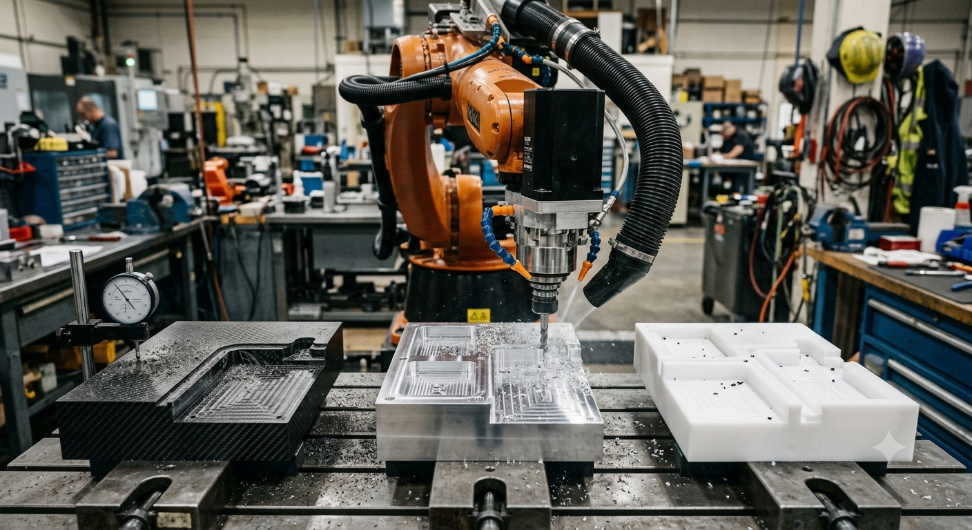

One of the first questions asked when evaluating a robotic machining cell is simple: What tolerance can the system achieve?
The realistic answer is that robotic milling tolerances cannot be defined by one universal number. Final part accuracy depends on the material, component size, robot posture, cutting forces, spindle performance, tool selection, calibration method, fixturing, and machining strategy.
For suitable large-format applications, a properly engineered robotic cell may maintain dimensional results within a few tenths of a millimeter. However, this should be treated as an application-specific planning range rather than a guaranteed specification for every geometry, material, or point within the working envelope.
At Robotic Hi-Tech Solutions, tolerance discussions begin with the complete machining process—not only with the repeatability value listed in the robot manufacturer’s technical data.
Why Robotic Milling Tolerances Differ from Robot Repeatability
Robot specifications frequently include a repeatability value. This indicates how closely the robot can return to a previously taught position under defined test conditions.
Repeatability does not automatically describe the complete accuracy of a machining process. The ISO 9283 industrial robot performance standard distinguishes between criteria such as pose accuracy, pose repeatability, path accuracy, and path repeatability.
- Absolute positioning accuracy
- Toolpath accuracy under cutting load
- Dimensional accuracy of the finished component
- Accuracy throughout the entire working envelope
- Surface quality during milling
A robot may return consistently to the same position while still following a path that differs slightly from the programmed CAD geometry. Kinematic errors, payload data, tool-center-point calibration, thermal conditions, and structural deflection can all affect the final result.
During machining, cutting forces introduce an additional source of error. An articulated robot is generally less rigid than a conventional machine-tool structure. As the tool engages the material, the robot, spindle, tool holder, cutter, fixture, and workpiece can all deform.
For this reason, final tolerance must be evaluated at the part level rather than inferred from robot repeatability alone.
Realistic Robotic Milling Tolerances by Material
The following ranges are practical starting points for project evaluation. They are not acceptance guarantees. Every application should be validated through simulation, test cuts, dimensional inspection, and, when appropriate, a formal machining trial.
Composite Materials: Lower Cutting Forces but Material-Specific Risks
Composite trimming, drilling, and routing are among the most established applications for robotic machining. Glass-fiber-reinforced plastic, carbon-fiber-reinforced polymer, and similar materials can often be processed with lower cutting forces than structural metals.
Under controlled conditions, robotic milling tolerances of approximately ±0.2 mm to ±0.5 mm may be realistic for many large composite trimming and contouring operations.
Performance depends strongly on:
- Part dimensions and geometry
- Fixture location and rigidity
- Condition and geometry of the cutting tool
- Robot calibration and cell referencing
- Toolpath direction and feed rate
- Laminate construction and fiber orientation
- Accessibility and robot posture
Lower cutting forces can reduce robot deflection, but composites present other challenges. Delamination, fiber pullout, fraying, abrasive tool wear, and local material damage can affect edge quality and dimensional consistency.
The component may also contain residual stress from molding or curing. After material is removed—or after the part is released from the fixture—it may relax or spring back. A dimension that was correct while clamped can therefore change after unloading.
Robotic machining is particularly effective for composite edge trimming, routing, drilling, mold preparation, and finishing when the tolerance requirement is compatible with the complete process.
Aluminum: Greater Dependence on Cell Rigidity
Aluminum machining normally generates higher cutting loads than composite trimming. Although aluminum is considered machinable, robotic milling performance depends heavily on controlling force, heat, chip evacuation, and vibration.
For finishing operations on large aluminum components, robotic milling tolerances of approximately ±0.1 mm to ±0.3 mm may be feasible in selected, well-controlled areas of the robot workspace.
This level of performance generally requires:
- Stable robot postures
- Conservative radial and axial engagement
- A rigid spindle and tool-holder interface
- Limited tool stick-out
- Effective chip evacuation and cooling
- Balanced finishing tools
- Rigid part support
- Calibrated base, tool and workpiece frames
- Validated roughing and finishing strategies
The same cell may not produce identical accuracy in every robot configuration. Accuracy and stiffness can deteriorate when the robot works near maximum reach, crosses wrist singularities or machines with an extended and mechanically unfavorable posture.
Heavy roughing also creates different conditions from light finishing. Aggressive material removal can increase structural deflection, chatter, and thermal variation. A common strategy is to leave a controlled machining allowance during roughing and remove it with lighter finishing passes.
Requirements consistently tighter than approximately ±0.1 mm across a very large envelope often favor a rigid CNC gantry, a hybrid machining architecture, or an additional metrology and compensation system.
Engineering Plastics: Low Forces with Thermal Sensitivity
Engineering plastics can be suitable for robotic milling because cutting forces are often moderate. Typical applications include prototypes, tooling boards, patterns, fixtures, large polymer components, and trimmed thermoformed parts.
Depending on the polymer, geometry, and cutting strategy, robotic milling tolerances comparable to those achieved in composite machining may be possible.
However, the term “engineering plastic” covers materials with very different behavior. Some polymers expand significantly with temperature, soften during cutting, absorb moisture, or deform under clamping pressure.
Important process variables include:
- Coefficient of thermal expansion
- Material temperature before inspection
- Heat generated at the cutting edge
- Chip evacuation
- Fixture pressure
- Wall thickness
- Tool sharpness and flute geometry
Excessive heat can produce dimensional drift, melted chips, poor edges, or material buildup on the cutter. Sharp tools, suitable feeds, and controlled cooling help reduce these effects.
7 Factors That Determine Robotic Milling Tolerances
1. Robot Posture and Workspace Position
An articulated robot does not have uniform stiffness throughout its envelope. Compact configurations are often more stable than fully extended positions.
Toolpath planning should therefore evaluate more than reachability. It should also consider joint configuration, directional stiffness, singularities, and the orientation of cutting forces.
2. Cutting Forces
Tool diameter, flute count, depth of cut, radial engagement, spindle speed, feed rate, and material properties determine the forces transmitted into the cell.
Reducing engagement and separating roughing from finishing can improve dimensional consistency.
3. Calibration and Reference Accuracy
Accurate base frames, work-object frames, and tool-center-point data are essential. Factory calibration can improve the robot’s absolute positioning performance, while field calibration can account for the installed cell. ABB explains in its Absolute Accuracy documentation how calibrated robot models reduce differences between programmed and physical positions.
Laser trackers, photogrammetry systems, optical measurement devices, and probing routines may be used to identify or compensate for geometric errors.
Calibration improves the relationship between the programmed model and the physical cell, but it does not eliminate deflection caused by machining forces.
4. Fixture and Workpiece Stability
A highly calibrated robot cannot compensate for a part that moves, vibrates, or deforms during machining.
The fixture should support the workpiece near critical cutting areas without introducing excessive clamping distortion. Thin panels, flexible molds, and large composite skins may require distributed support, vacuum tooling, or adjustable locators.
5. Spindle, Tool Holder and Cutter
Spindle runout, bearing condition, tool-holder quality, cutter balance, and tool stick-out influence both accuracy and surface finish.
A long tool may improve accessibility but reduce system stiffness. When long reach is unavoidable, cutting parameters and toolpath orientation should be adjusted accordingly.
6. Thermal Conditions
Temperature affects the robot, spindle, workpiece, and fixture. Aluminum and polymers can change dimensions as their temperature changes, while spindle warm-up can influence runout and tool position.
Inspection conditions should therefore be defined as part of the tolerance plan, particularly for large components or temperature-sensitive materials.
7. Measurement and Compensation Strategy
The required tolerance must be measurable. Probing, laser scanning, photogrammetry, or coordinate measurement can be integrated into the validation process.
For high-value components, an iterative workflow may be appropriate:
- Machine the initial geometry.
- Measure the relevant features.
- Calculate dimensional deviation.
- Compensate the finishing path.
- Machine and inspect the final surface.
This approach can improve local accuracy, although it adds programming, measurement, and cycle-time requirements.
Can Calibration Guarantee the Required Tolerance?
Calibration is necessary for accurate robotic machining, but it should not be treated as a complete solution.
Reliable robotic milling tolerances require calibration to work together with stable cutting parameters, suitable robot postures, and rigid part support.
Geometric calibration helps correct differences between the robot’s mathematical model and its physical structure. Tool-center-point calibration improves knowledge of the cutter position. Workpiece calibration aligns the programmed part with its real position in the cell.
These procedures address positioning errors. They do not fully correct dynamic errors caused by cutting forces, chatter, fixture movement, tool wear, or thermal deformation.
The strongest results are achieved when calibration is combined with:
- Stiffness-aware toolpath planning
- Controlled cutting engagement
- Stable fixturing
- Tool-condition monitoring
- Dimensional inspection
- Process-specific compensation
When a CNC Gantry Remains the Better Choice
Robotic milling is not intended to replace every CNC machine. A conventional or hybrid gantry system may remain preferable when the application requires:
- Micrometric feature control
- Very tight tolerances over long distances
- Heavy and continuous metal removal
- High structural stiffness in every axis
- Precision bores, sealing surfaces or bearing fits
- Machine-tool-level volumetric accuracy throughout the envelope
The correct decision is not based on whether robots or CNC machines are universally better. It is based on matching the architecture to the part, production volume, material-removal requirement, tolerance, flexibility, and investment target.
When Robotic Milling Provides the Strongest Value
A robotic cell becomes particularly attractive when:
- The component is too large or complex for an economical conventional machine
- Several part geometries must be processed in one cell
- Five-axis or six-axis accessibility is important
- Cutting forces are moderate
- The process involves trimming, routing, drilling or light milling
- The required tolerance falls within an engineered robotic process window
- Flexible automation is more important than micrometric accuracy
For these applications, the robot’s large working envelope and configuration flexibility can provide a cost-effective alternative to a dedicated gantry platform.
How to Define a Defensible Tolerance Requirement
Instead of asking only, “What tolerance can the robot achieve?”, the project team should define:
- Which dimensions are functionally critical
- Whether tolerances are local or apply across the complete part
- Whether inspection occurs while the part is clamped or after release
- The temperature at which dimensions must be verified
- Required surface finish and edge quality
- Acceptable process capability and rejection rate
- Measurement uncertainty
- Whether compensation or re-machining is permitted
A representative test part is often more valuable than a generic accuracy promise. It allows the integrator and customer to validate real geometry, material, tooling, posture, fixturing, and measurement conditions before final acceptance.
Checklist Before Approving Robotic Milling Tolerances
- Material properties and machining behavior have been reviewed.
- Critical and noncritical dimensions have been separated.
- Tolerances are defined for the final unclamped part.
- Robot reach and stiffness have been evaluated along the complete path.
- Roughing and finishing requirements have been separated.
- Tool length, runout, and balance have been validated.
- Fixture deformation and vibration have been assessed.
- Calibration and cell-referencing methods have been selected.
- Inspection temperature and measurement uncertainty are defined.
- Representative machining trials are included in the validation plan.
Conclusion
There is no single value for robotic milling tolerances that applies to every application. Real performance is determined by the material, component geometry, cutting forces, robot posture, calibration, tooling, fixturing, and inspection strategy.
As an initial planning reference, large composite and engineering-plastic operations may often target tolerances within several tenths of a millimeter. Controlled aluminum finishing may achieve tighter results in suitable areas of the working envelope. However, every figure must be validated against the real part and process.
When the tolerance requirement matches the capabilities of an engineered robotic cell, robotic machining can provide an effective alternative to a large CNC gantry—especially when workspace, flexibility, and investment efficiency are central to the project.
Robotic Hi-Tech Solutions designs robotic milling cells around the required part quality, material behavior, and production process. Contact our engineering team to evaluate whether your tolerance requirements are suitable for robotic machining.
FAQ’s
Can robotic milling match CNC machining accuracy?
Robotic milling can match the required accuracy of some large-format trimming, routing and light-milling applications. However, rigid CNC machines normally remain more suitable for micrometric features, precision bores, heavy metal removal and consistently tight tolerances across a large volume.
Are composites easier to machine with a robot?
They often generate lower cutting forces than metals, which can reduce robot deflection. Nevertheless, abrasive fibers, delamination, tool wear, springback and residual stress must still be controlled.
Does robot calibration improve machining tolerance?
Yes. Calibration can improve absolute positioning, tool-center-point definition and alignment between the digital model and physical cell. It does not, however, eliminate errors caused by cutting-force deflection, vibration, fixture movement or thermal expansion.
Can robotic milling consistently achieve ±0.1 mm?
It may be possible in selected finishing operations and favorable robot postures, but it should not be assumed across every material, toolpath or point in a large envelope. A machining trial and dimensional capability study are required before making a production commitment.
Why does tolerance change across the robot workspace?
Robot stiffness varies with joint position and tool orientation. A compact posture may resist machining forces better than a fully extended configuration. The direction of the cutting load relative to the robot joints also affects deflection.
How does part size affect robotic milling accuracy?
Larger parts normally require longer toolpaths and a wider range of robot configurations. They may also experience greater fixture movement, thermal variation and material relaxation. Local features can therefore be more accurate than dimensions measured across the entire component.
Can measurement systems compensate for machining errors?
External metrology, probing and scanning can identify deviations and support compensated finishing paths. Compensation can improve results, but it adds measurement time and cannot correct an unstable cutting process by itself.
Should tolerance be checked before or after unclamping?
Functional dimensions should normally be validated in the condition specified for the finished component. If the part can spring back or relax after release, inspection only while it remains clamped may not represent its final geometry.