English
 Italiano
 Українська
 Русский
 Español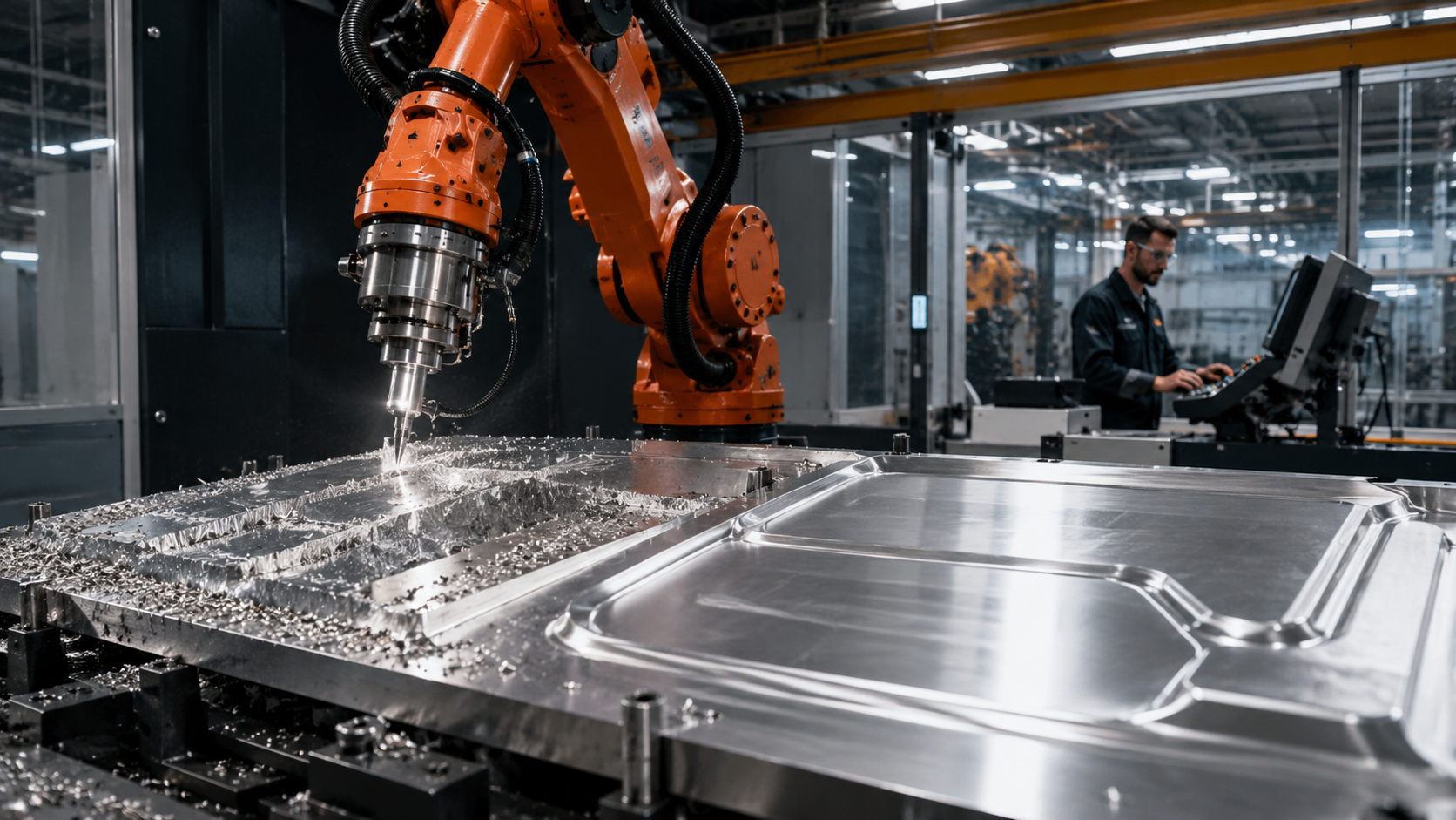

How to control feeds, speeds, engagement, robot posture, and thermal behavior when moving from material removal to surface finishing.
Robotic milling cutting parameters cannot remain unchanged when a process moves from roughing to finishing. Roughing prioritizes controlled material removal, while finishing exposes even minor problems involving vibration, tool balance, robot posture, thermal movement, and fixture compliance.
The transition is therefore more than a reduction in feed rate. It requires a coordinated change in tool engagement, spindle speed, feed per tooth, acceleration, step-over, remaining stock, and robot configuration. When these variables are adjusted systematically, a robotic milling cell can produce a more stable and repeatable surface across large components.
At Robotic Hi-Tech Solutions, we treat roughing and finishing as two connected but mechanically different operating conditions. The finishing result is not created only by the final pass. It is also influenced by the stock condition, heat, residual stresses, tool condition, and surface uniformity produced during roughing.
Why Robotic Milling Cutting Parameters Must Change
A conventional machining program may separate roughing and finishing through different toolpaths, but changing the path alone is not sufficient. The mechanical objective of each stage is different.
During roughing, the tool normally removes a larger volume of material. Cutting forces, spindle load, chip formation, and thermal accumulation are therefore major concerns. During finishing, material engagement becomes lighter, but the process becomes much more sensitive to motion irregularities and changes in system stiffness.
Industrial robots also behave differently from rigid gantry CNC machines. Their stiffness varies with joint configuration, working-envelope position, tool orientation, and cutting-force direction. A parameter set that performs well near the robot base may create chatter or visible surface marks when the arm is extended.
For this reason, the transition must be engineered around the complete system:
- The industrial robot and its posture
- The spindle and tool-holder assembly
- The cutting tool and its effective length
- The workpiece and fixture
- The material being machined
- The CAM strategy and post-processor
- The programmed acceleration and path blending
Step 1: Stabilize Roughing Before Increasing Productivity
The purpose of roughing is not simply to achieve the highest possible material-removal rate. In robotic machining, the first objective should be repeatable material removal without excessive deflection, vibration, spindle overload, or unpredictable chip recutting.
Aggressive axial and radial engagement values that work on a rigid machining center may produce unstable forces when transferred directly to an articulated robot. The robot can deflect under load, and the direction and magnitude of that deflection can change as the arm moves through the workspace.
Control tool engagement
Adaptive, dynamic, or trochoidal strategies can help maintain a more consistent engagement angle. These strategies reduce sudden load changes and can be particularly useful when machining corners, pockets, or varying stock conditions.
Engineering teams should evaluate:
- Radial width of cut
- Axial depth of cut
- Feed per tooth
- Tool-entry and exit strategy
- Direction of the resulting cutting force
- Spindle load during different robot postures
A controlled tool load usually produces more useful production data than an aggressive test performed in only one favorable position.
Maintain effective chip evacuation
Chip recutting can change cutting forces, increase tool temperature, damage cutting edges, and reduce surface consistency. Air blast, minimum-quantity lubrication, extraction, or another appropriate cooling and evacuation method should be matched to the material and cell design.
The machining process should also be inspected in areas where chips may accumulate around fixtures, deep geometries, or enclosure structures.
Step 2: Leave a Uniform Finishing Allowance
One of the most important robotic milling cutting parameters is not a spindle or feed value. It is the amount and uniformity of stock left for the finishing operation.
If roughing leaves an inconsistent allowance, the finishing tool experiences changing engagement. Cutting forces then rise and fall as the tool moves across the part. In a robotic system, these variations can produce local deflection, surface waviness, transition marks, or dimensional inconsistency.
The roughing strategy should leave enough material to remove roughing marks and minor geometric errors, but not so much that the finishing pass behaves like another roughing operation.
Before finishing, verify that:
- The remaining stock is reasonably uniform
- Deep roughing marks will not overload the finishing tool
- No uncut islands remain in critical areas
- Edges have enough support for the final pass
- The workpiece has not shifted inside the fixture
For complex parts, a semi-finishing operation may be necessary. Semi-finishing creates a more uniform surface and allows the final tool to work under predictable engagement conditions.
Step 3: Introduce a Controlled Transition Phase
Moving directly from aggressive roughing to the final finishing pass can transfer heat, vibration, tool wear, and geometric irregularities into the most sensitive stage of the process.
A controlled transition provides an opportunity to inspect and stabilize the cell. Depending on the application, it may include a semi-finishing pass, a tool change, chip removal, spindle inspection, workpiece measurement, or a short stabilization period.
Check thermal behavior
Roughing generates heat in the cutting tool, spindle, workpiece, chips, and surrounding structure. If finishing begins while the part is still changing dimensionally, the measured geometry may differ after the component returns to a stable temperature.
The required response depends on the material, part size, tolerance, cycle time, and environmental conditions. The objective is not to introduce unnecessary waiting time. It is to determine whether thermal variation is large enough to affect the required result.
Inspect the cutting system
The transition point is also an appropriate time to verify:
- Cutting-edge condition
- Built-up material on the tool
- Tool-holder cleanliness
- Tool runout
- Spindle vibration
- Fixture security
- Workpiece movement or deformation
A damaged or contaminated tool should not be carried into finishing simply because it completed the roughing operation.
Step 4: Recalculate Feed, Speed, and Engagement
Finishing parameters should be calculated as a separate operating condition. Reducing the programmed feed without considering chip load can cause rubbing rather than effective cutting. Increasing spindle speed without checking balance, tool limits, and spindle capability can also introduce new vibration.
The main variables include:
- Cutting speed: selected for the material, tool substrate, coating, and cutting condition
- Spindle speed: derived from cutting speed and effective tool diameter
- Feed per tooth: maintained within a range that supports clean chip formation
- Feed rate: calculated from spindle speed, tooth count, and feed per tooth
- Radial engagement: reduced to control lateral cutting force
- Axial depth: selected according to geometry, tool stiffness, and remaining stock
Tool-manufacturer recommendations provide an initial reference, not an automatically validated robotic parameter set. The final values must account for robot stiffness, spindle mounting, tool stick-out, fixture behavior, and the position of the cut inside the workspace.
Avoid reducing feed rate in isolation
A common commissioning mistake is to slow the robot whenever surface defects appear. This may reduce some dynamic effects, but it can also lower chip thickness excessively, increase rubbing, generate heat, or shorten tool life.
Instead, change one controlled variable at a time and document the result. A practical test sequence may adjust feed per tooth, spindle speed, radial engagement, or cutting direction independently before combining changes.
Step 5: Optimize Step-Over and Toolpath Direction
Step-over directly affects scallop height, machining time, and the number of tool engagements across the surface. A smaller step-over can improve the theoretical finish, but it also increases cycle time and does not automatically eliminate vibration-related marks.
The appropriate value depends on:
- Tool diameter and geometry
- Surface curvature
- Required roughness
- Material response
- Robot posture along the path
- Direction of cutting forces
On free-form surfaces, the effective cutting diameter of a ball-nose tool changes with the contact point. CAM calculations should consider this behavior when establishing spindle speed, step-over, and tool orientation.
Evaluate climb and conventional cutting behavior
The selected cutting direction changes how forces act on the robot, tool, and workpiece. One direction may load the robot toward a stiffer configuration, while the opposite direction may encourage deflection or excite a flexible structural mode.
Test cuts should therefore evaluate not only visual finish but also cutting-force direction, dimensional deviation, and consistency across the complete toolpath.
Step 6: Match the Finishing Path to Robot Dynamics
Robotic milling cutting parameters cannot compensate fully for an unfavorable robot configuration. Finishing should be planned in areas and postures that provide suitable stiffness whenever the component geometry allows it.
Robot motion should be reviewed for:
- Excessive arm extension
- Near-singular configurations
- Large wrist rotations during cutting
- Abrupt changes in orientation
- Acceleration peaks at corners
- Frequent speed reductions
- Changes in force direction
A smooth CAM curve does not guarantee smooth robot motion. The post-processor, controller interpolation, path-point density, blending settings, and orientation strategy influence how the industrial robot executes the programmed path.
Finishing programs should use controlled acceleration, deceleration, and path blending. Excessive exact-stop commands can leave witness marks, while excessive blending may reduce geometric accuracy. The correct balance must be validated against both surface and dimensional requirements.
Beyond process stability and surface quality, robotic milling cells must also be designed around appropriate safeguarding, risk assessment, and controlled access. For official guidance, consult OSHA’s Industrial Robots and Robot System Safety guidance.
Step 7: Validate Parameters with Measured Results
The final optimization stage should be based on measured evidence rather than visual judgment alone. A surface may appear acceptable under one lighting condition while still failing the required roughness or dimensional tolerance.
Depending on the application, validation may include:
- Surface roughness measurement
- Dimensional inspection
- Spindle-load monitoring
- Vibration measurement
- Tool-wear inspection
- Thermal measurement
- Cycle-time analysis
- Comparison across different robot postures
Each test should record the tool, tool stick-out, spindle speed, feed per tooth, feed rate, step-over, cutting depth, robot position, material batch, and measured result. This creates a repeatable process window instead of a single successful trial.
How Material Changes the Optimization Strategy
Aluminum
Aluminum finishing requires effective chip evacuation, sharp cutting edges, and controlled chip thickness. Built-up material on the cutting edge can damage surface quality, while unstable robot motion can create chatter patterns or changes in texture.
High spindle speed may be useful, but it must remain compatible with the tool, holder, spindle, and balance quality. Feed reduction should not be so severe that the cutting edge begins to rub.
Composite materials
Composite finishing often prioritizes edge integrity, fiber condition, dust extraction, and control of local damage. Tool geometry, tool wear, cutting direction, and support near trimmed edges are critical.
Because the material may be anisotropic, forces and edge quality can change with fiber orientation. Parameters should therefore be validated in more than one cutting direction.
Plastics, foam, and tooling board
These materials generally require lower cutting forces than aluminum, but they can still reveal trajectory marks over large surfaces. Heat generation, chip evacuation, tool sharpness, and surface waviness remain important.
A parameter set that removes material easily may still be unsuitable when the component will later be painted, coated, polished, or used as a mold.
Common Mistakes When Moving from Roughing to Finishing
Many finishing problems originate before the final tool reaches the component. Common mistakes include:
- Using one parameter philosophy for both roughing and finishing
- Leaving an irregular finishing allowance
- Starting the final pass with a worn roughing tool
- Reducing feed without checking feed per tooth
- Increasing spindle speed without verifying balance
- Ignoring temperature changes after heavy roughing
- Finishing near maximum robot extension without testing
- Using abrupt stops or orientation changes on visible surfaces
- Measuring only one area of a large component
- Changing several parameters simultaneously without recording them
A structured commissioning process isolates each variable and establishes a validated operating window for production.
Checklist Before Approving Final Finishing Parameters
- Roughing load is stable and repeatable
- A uniform finishing allowance has been confirmed
- Thermal behavior has been evaluated
- The workpiece and fixture remain stable
- The finishing tool is sharp and undamaged
- Tool runout and holder condition are acceptable
- Spindle speed remains within approved limits
- Feed per tooth supports effective cutting
- Radial and axial engagement have been optimized
- Step-over meets surface and cycle-time requirements
- Robot posture has been evaluated across the path
- Acceleration and path blending have been tested
- Surface roughness has been measured
- Dimensional accuracy has been validated
- The approved parameters have been documented
Conclusion
Robotic milling cutting parameters must be adapted deliberately when transitioning from roughing to finishing. The correct approach combines stable roughing, a uniform stock allowance, thermal control, clean tooling, an appropriate chip load, controlled engagement, a favorable robot posture, and measured validation.
Finishing should not be treated as an isolated final pass. Surface quality is developed throughout the machining process, beginning with how roughing forces, heat, remaining stock, and robot motion are controlled.
When the transition is engineered systematically, robotic milling cells can deliver more consistent surfaces, predictable cycle times, and repeatable results on large aluminum, composite, plastic, and advanced-material components.
Optimize Your Robotic Milling Process
Robotic Hi-Tech Solutions designs and integrates large-format robotic milling cells using industrial robots, high-speed spindles, material-specific tooling, CAM strategies, and production validation.
Contact our engineering team to evaluate cutting parameters, robot posture, spindle integration, fixturing, and surface-finish requirements for your application.
FAQ’s
Can robotic systems perform aggressive roughing?
Yes, when tool engagement, chip evacuation, robot posture, spindle capacity, and fixture stiffness are properly controlled. The objective should be stable material removal rather than the highest theoretical removal rate.
Why does finishing reveal vibration more clearly?
Finishing creates the final visible surface. Small changes in robot motion, tool deflection, spindle vibration, or engagement can therefore leave measurable or visible marks even when the cutting forces are lower.
Should finishing always be performed in the stiffest robot posture?
Finishing should use favorable robot postures whenever geometry and cell layout permit. However, the complete path must be tested because stiffness changes continuously as the robot moves.
Should feed rate always be reduced for finishing?
No. Feed rate should be recalculated with spindle speed, tooth count, feed per tooth, tool geometry, and material. Excessively low feed can cause rubbing, heat, and premature tool wear.
Is a higher spindle speed always better for surface finish?
No. Higher spindle speed may improve some cutting conditions, but it can also excite vibration or exceed tool, holder, or spindle limits. It must be validated with the corresponding feed and engagement values.
How much material should be left for finishing?
There is no universal value. The allowance depends on material, tool diameter, roughing accuracy, part stiffness, required tolerance, and surface condition. Uniformity is generally more important than selecting one fixed value for every application.
Is semi-finishing necessary in robotic milling?
Semi-finishing is useful when roughing leaves irregular stock, deep tool marks, thermal distortion, or geometry that would overload the final tool. It creates more predictable conditions for finishing.
How should finishing parameters be validated?
Use controlled test cuts and record spindle speed, feed per tooth, engagement, tool, robot posture, vibration, roughness, dimensional results, and cycle time. Parameters should be tested across representative areas of the working envelope.