English
 Italiano
 Українська
 Русский
 Español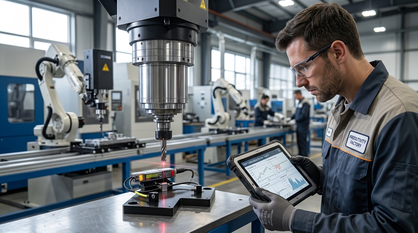

TCP calibration errors become dimensional errors because the controller calculates every programmed tool position from an incorrect tool frame. If the stored Tool Center Point does not match the cutter tip or another defined cutting point, the robot places that point somewhere other than the programmed location. The effect can appear as an offset, an angle-dependent deviation, or a path that changes when tool orientation changes.
In robotic machining, this matters at drilling centers, trimmed edges, pocket boundaries, and transitions between tool orientations. TCP calibration errors do not automatically explain every rejected part, but they should be investigated when deviations follow the tool direction, change after a spindle or holder replacement, or become larger during wrist reorientation.
This article explains how TCP position and orientation errors reach the workpiece, how to distinguish them from other error sources, and what to verify before editing a machining program.
What the TCP represents in robotic machining
TCP position
The TCP is a defined point associated with the end-of-arm tool. For a spindle, it may be assigned to the cutter tip or another point required by the programming method. Its coordinates are stored relative to the robot flange or tool mounting frame.
A tool frame also has an orientation. Its axes tell the controller how the tool is directed, not merely where its tip is located. CAM output and robot motion commands rely on that orientation when they prescribe a cutting direction, surface normal, lead angle, or approach vector.
How TCP calibration errors enter the programmed path
The controller combines robot joint positions with the base, work-object, and tool transformations to locate the active TCP. A wrong tool transformation therefore changes the physical pose produced by an otherwise correct target. The programmed coordinates can remain unchanged while the cutter reaches a different point on the part.
Translation error
If the stored TCP is displaced from the cutting point, a translation error may shift a feature. The shift depends on tool pose: an offset expressed in tool coordinates rotates with the tool and may produce different part-coordinate errors along a multi-axis path.
Orientation error
If the stored tool axes are tilted relative to the real spindle axis, commanded orientations are also tilted. At a point away from the rotation center, an angular discrepancy creates lateral displacement that increases with distance from that center.
Why TCP calibration errors change with robot orientation
TCP calibration errors often produce pose-dependent results. When the wrist rotates, an incorrectly defined tool offset rotates with it. A point that appears acceptable in one posture can move away from the intended feature in another, even though robot repeatability appears stable.
This helps distinguish a TCP error from a constant work-object translation. During reorientation around a fixed reference, the working point should remain at the reference. Visible orbiting indicates that the stored and physical points do not coincide.
Where dimensional errors appear on machined parts
TCP calibration errors can displace hole centers or alter the approach angle in drilling. In trimming, they can move the edge relative to the programmed contour. In surface machining, they can change the cutter contact position.
Compare errors at multiple poses and locations. A deviation that changes with wrist orientation points toward tool data. An error concentrated in one workspace region may also involve robot calibration, structural effects, or the work frame.
Cells with an external track require additional checks because dimensional deviations may also originate in track alignment, robot-to-track calibration, or coordinated motion. The article Linear Axis Robotic Milling: 7 Critical Criteria for Better Performance explains how these variables interact with TCP and work-object calibration.
How to separate TCP errors from other error sources
Before concluding that TCP calibration errors are responsible, verify the work frame, base data, axis mastering, and kinematic calibration. Altering the TCP does not reliably correct errors originating in these other coordinate relationships.
Robot deflection, runout, cutter deflection, fixture movement, thermal change, backlash, and cutting parameters can also influence the result. Unlike a fixed calibration value, several vary with load, direction, speed, engagement, or temperature.
TCP calibration is only one contributor to dimensional stability. The article Why Repeatability Becomes the Critical Risk in Robotic Machining of Custom Geometries explains how calibration, tooling, fixtures, spindle behavior, and process conditions interact during machining validation.
Eight checks before changing the machining program
- Confirm the active tool data: verify that the program calls the TCP for the installed spindle, holder, and cutter.
- Inspect the tool assembly: check for looseness, changed tool length, cutter damage, spindle movement, or contaminated interfaces.
- Check the reference artifact: use a rigid, undamaged reference suitable for the manufacturer’s calibration method.
- Test several orientations: use sufficiently different wrist poses so a false TCP cannot appear correct from one direction.
- Review calibration quality: examine the reported result or residual, where available, using the manufacturer’s acceptance procedure.
- Verify tool orientation: check that the stored tool axes agree with the actual spindle axis and with the convention used by CAM and post-processing.
- Validate the work frame separately: confirm fixture location and work-object orientation without using TCP edits to absorb their errors.
- Run a controlled test: use safe speed, known geometry, and suitable measurement across several poses before production.
How to correct and validate the TCP
Recalibrate before retouching points.
Follow the manufacturer’s method for the controller and tool. Use the required poses, keep the reference stable, and avoid measurements from nearly identical orientations. Save the previous data and record the installed hardware.
After correcting confirmed TCP calibration errors, repeat the reorientation check and validate a known path or artifact at several poses and locations. One successful point cannot validate tool orientation, work data, robot kinematics, and process loading.
Do not retouch every point before checking the tool frame. Restoring the intended TCP may correct multiple paths consistently; point edits can conceal the source and conflict with later recalibration.
Safety and change control during calibration
Calibration may require manual motion near a reference, spindle, fixture, or workpiece. Apply the approved risk assessment, operating mode, speed limits, safeguarding, and energy-control procedures. OSHA’s industrial robot system safety guidance covers teaching, integration, testing, and maintenance hazards.
Record old and new TCP values, tool identification, method, date, reference, and validation result. Recheck after a collision, spindle removal, holder replacement, or another change to the tool relationship.
In cells with automatic tool changing, each cutter must be associated with the correct tool data and verified TCP. The article ATC Robotic Milling: Is Continuous Production Viable? examines tool-data management, TCP validation, holder compatibility, and monitoring after automatic changes.
For an application-specific review of tool frames and machining validation, contact Robotic Hi-Tech Solutions with the robot, controller, spindle, tooling, CAM workflow, and observed error pattern.
FAQ
Can a TCP error cause the same offset on every feature?
It can with constant tool orientation. When orientation changes, a tool-coordinate offset changes direction relative to the part, so the measured error may change.
Why does a point look correct until the wrist rotates?
The physical point and stored TCP may coincide in one pose but separate during rotation. Calibration therefore uses several distinct orientations around a stable reference.
Can robot repeatability prove that the TCP is correct?
No. A robot can return consistently to a pose calculated from incorrect tool data. Repeatability describes consistency; it does not independently validate the tool frame’s dimensional accuracy.
Does changing cutter length require a new TCP?
Yes, if the active TCP is defined at the cutting point and the effective length changes. Some workflows manage tool-length compensation separately, so the controller, CAM, and cell convention must be checked.
Can TCP correction compensate for spindle runout?
No. TCP data define a nominal frame. Runout is a mechanical rotation error and requires inspection of the spindle, holder, cutter, interfaces, and measurement method.
Should the work-object frame be recalibrated at the same time?
Only when evidence indicates it is wrong or the fixture relationship has changed. Verify the tool and work frames separately so one adjustment does not hide an error in the other.
When should TCP calibration be checked again?
Check it after a collision, tool or spindle removal, holder or cutter changes that alter the defined point, maintenance affecting the tool mount, or an unexplained pose-dependent dimensional change.
Is one machined test feature enough for validation?
No. Validate multiple poses and separate unloaded positioning checks from cutting results, which also include mechanical and process effects.