English
 Italiano
 Українська
 Русский
 Español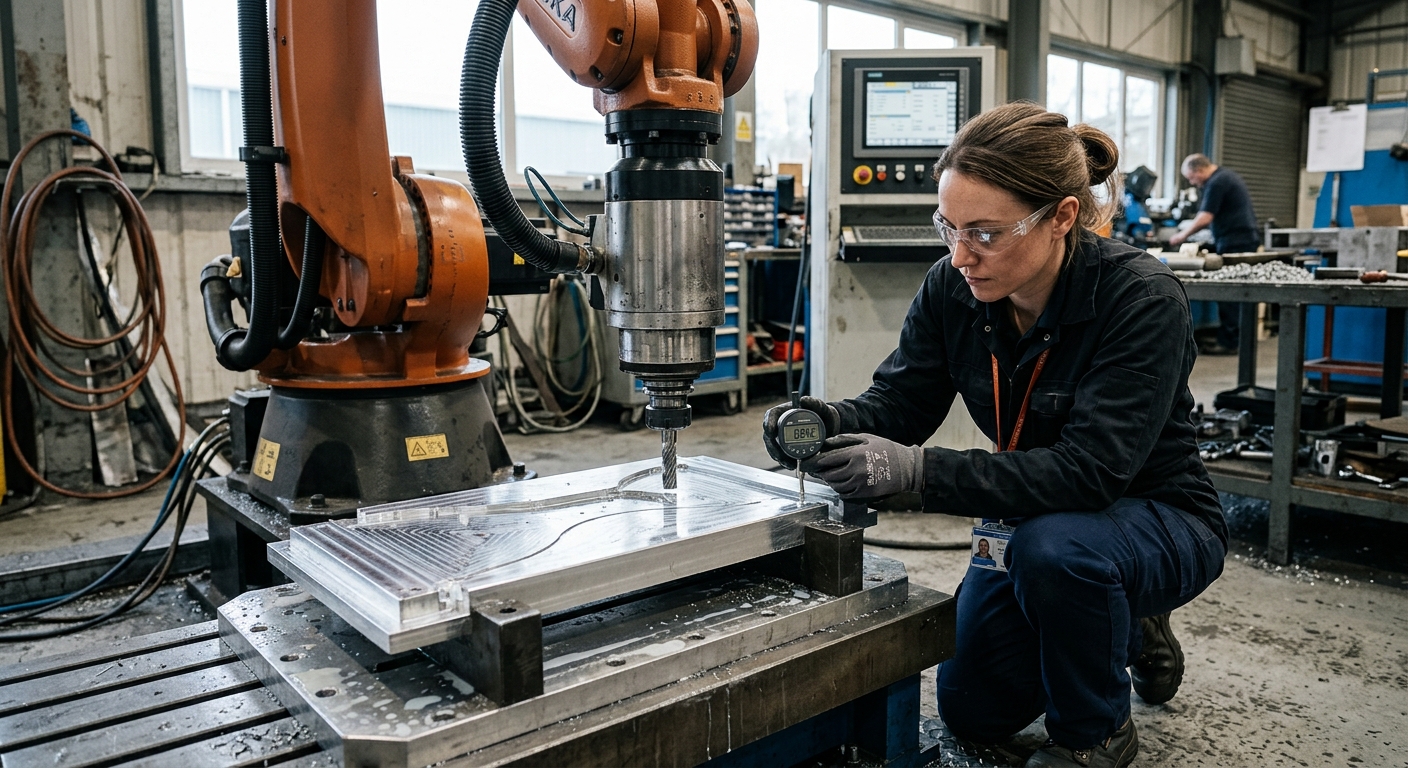

Robot contour error often matters more than a single position-accuracy value when an industrial robot is used for milling. Position accuracy indicates how closely the robot reaches a commanded pose under defined test conditions. Contour error describes how far the tool departs from the programmed path while several robot axes move together.
The distinction affects how engineers evaluate a robotic machining cell. A robot may reach isolated points consistently but still deviate from a curved or changing toolpath because of axis coordination, structural deflection, vibration, calibration errors, control behavior, or cutting forces. Those deviations can affect profile accuracy, transitions between surfaces, edge location, and surface finish.
This article explains how the two measures differ, why static specifications cannot predict every machining result, and which tests provide useful evidence. The practical answer is to evaluate position accuracy for locating features and establishing reference points, while using path measurements and machined-part inspection to assess continuous milling performance.
Why Robot Contour Error and Position Accuracy Are Different
Position accuracy compares a commanded pose with the pose that the robot actually reaches. A pose includes position and orientation. Testing normally requires defined loads, speeds, locations, coordinate systems, and environmental conditions because the result can change when those conditions change.
Contour error concerns continuous motion. It is the deviation between the intended contour and the path followed by the tool centre point. The relevant deviation may be normal to the contour rather than simply measured along one Cartesian axis.
Static positioning does not describe the complete toolpath
A point test can reveal an offset at a selected location, but it does not reproduce coordinated movement through a curve. During contouring, several joints may accelerate, decelerate, or reverse direction. This introduces dynamic effects that an isolated positioning test may not expose.
What Does Robot Position Accuracy Reveal?
Position accuracy is useful when the process depends on reaching known locations. Examples include approaching a fixture datum, positioning a probe, entering a predrilled feature, or aligning the cutter with a workpiece reference. A systematic offset can shift these operations even when the robot repeats the same motion reliably.
Accuracy and repeatability are not interchangeable.
Accuracy describes closeness to the commanded pose. Repeatability describes how closely the robot returns to previously reached poses under the same conditions. A robot can be repeatable but inaccurate if it repeatedly reaches the same location with a consistent offset.
Calibration can reduce certain systematic position errors by improving the relationship between the robot model and its physical geometry. However, calibration does not remove compliance, backlash, thermal effects, fixture movement, spindle deflection, or errors in the workpiece and tool coordinate systems.
What Does Robot Contour Error Reveal?
Robot contour error shows how well the complete motion system follows a programmed geometry. It is especially relevant to arcs, free-form surfaces, blended corners, and paths that require simultaneous changes in tool position and orientation.
Robot contour error is not necessarily constant along the path. It may increase near joint reversals, rapid changes in direction, regions with low structural stiffness, or configurations where small joint errors produce larger Cartesian deviations at the tool.
Path accuracy and finished-part accuracy are related but different.
Path measurement records robot or tool motion, normally without directly describing material removal. Finished-part inspection includes the combined influence of path motion, cutter geometry, spindle condition, cutting forces, workholding, thermal behavior, material response, and measurement uncertainty.
A measured path deviation may therefore indicate a motion problem without predicting the exact dimensional error on the part. Conversely, a part may show an error caused by tool deflection or fixture movement even when unloaded path tracking appears acceptable.
Why Contour Error Matters in Robotic Milling
Milling requires the cutting edge to remain within an acceptable relationship to the programmed surface. A path deviation toward the part can remove excess material. A deviation away from it can leave stock. The result depends on the direction of the error, tool geometry, tool orientation, and machining strategy.
Robot contour error can also vary with feed rate. Higher commanded speeds may require greater joint acceleration, particularly on small-radius curves or abrupt directional changes. Reducing speed may improve tracking in some conditions, but it cannot correct every geometric, calibration, or stiffness problem.
Tool orientation adds another source of dimensional variation.
An angular error at the robot flange produces a position change at the cutting edge when the tool extends beyond the flange. The effect depends on the distance from the flange to the cutting point. For this reason, TCP definition and orientation control must be evaluated together with translational path behavior.
Which Factors Influence Contouring Performance?
Contour performance results from the complete cell rather than one robot specification. Robot configuration, payload, wrist inertia, tool length, axis direction changes, trajectory generation, speed, acceleration settings, and controller functions can all influence the measured path.
The mechanical installation also matters. Movement in the robot base, pedestal, fixture, spindle mount, or tool holder changes the relationship between the cutter and the part. The guide on how foundation stiffness affects industrial robot performance explains why base deflection and structural vibration can contribute to path deviation.
Cutting forces change the result.
An unloaded test is valuable for isolating motion behavior, but milling introduces force. Force magnitude and direction vary with engagement, tool geometry, material, spindle speed, feed, and toolpath. Because robot stiffness changes across its workspace, the same cutting condition can produce different deflection at different poses.
The article 7 Critical Factors for Robotic Milling Stability explains how calibration, tooling, fixtures, structural stiffness, and measurement influence dimensional results beyond the robot’s nominal accuracy.
How Should Robot Contour Error Be Measured?
A robot contour error test should reproduce the relevant workspace region, tool orientation, payload, velocity, and trajectory type. Measuring a convenient circle near the robot base may not characterize a large free-form path executed near the edge of the working envelope.
Suitable measurement systems depend on the required uncertainty, path geometry, access, and test objective. Possible approaches include external metrology, calibrated artefacts, trajectory tests, and inspection of a machined test piece. The measurement method must have adequate resolution and a documented setup.
Use defined performance criteria.
ISO 9283 specifies performance criteria and related test methods for manipulating industrial robots, including pose and path characteristics. A standard test supports consistent comparison, but application-specific cutting trials remain necessary because standard robot tests do not reproduce every machining load or cell configuration.
Eight Checks for Evaluating a Robotic Milling Cell
- Define the required feature: identify whether acceptance depends on isolated hole locations, continuous profiles, surface form, orientation, or a combination of these characteristics.
- Specify the reference frame: document the robot base, work object, TCP, fixture datums, and measurement coordinate system used during testing.
- Reproduce the working region: test where the actual part will be machined, including robot postures that may have lower stiffness or difficult joint coordination.
- Use the production tool configuration: include the intended spindle, holder, cutter projection, cables, hoses, payload, centre of gravity, and relevant wrist inertia.
- Test representative trajectories: include straight segments, curves, changes in orientation, blended transitions, and joint reversals found in the production program.
- Compare relevant speeds: measure at the intended feed rate and, when troubleshooting, repeat at lower rates to identify speed-dependent path behavior.
- Separate loaded and unloaded tests: first examine programmed motion without cutting, then use controlled cutting trials to identify force-related deflection and process effects.
- Inspect the machined result: measure the features and surfaces that correspond to the actual acceptance criteria instead of relying only on controller data or nominal robot specifications.
How Should the Results Be Interpreted?
A single robot contour error value can hide where and why a deviation occurs. Review the error along the path, its direction, its relationship to speed and robot configuration, and whether the behavior repeats over multiple runs.
Acceptance limits should come from the part requirement and the measurement method, not from a general expectation about robotic machining. The allocated error budget should also account for the tool, spindle, fixture, workpiece, calibration, thermal conditions, and inspection uncertainty.
Match corrective action to the observed error.
A consistent geometric offset may indicate a frame, TCP, calibration, or datum problem. Speed-dependent deviations may require trajectory or motion-setting review. Errors that increase during cutting may point to compliance, tool engagement, workholding, or spindle-related effects. Several causes can occur together.
For an application-specific review of accuracy requirements, test conditions, and cell configuration, engineers can contact Robotic Hi-Tech Solutions with the part geometry, material, tooling concept, required tolerances, and expected machining strategy.
FAQ
Is robot position accuracy enough to qualify a milling cell?
No. It provides useful pose information, but continuous-path tests and machined-part inspection are also needed to evaluate milling performance.
Can a repeatable robot still produce an inaccurate contour?
Yes. Repeatability at selected poses does not guarantee accurate coordinated motion or compensate for systematic path, calibration, or process errors.
Does lower feed rate always reduce contour error?
No. It may reduce some dynamic tracking errors, but geometric offsets, incorrect frames, compliance, backlash, and tool errors can remain.
Should contour testing be performed with or without cutting?
Both are useful. Unloaded testing isolates motion behavior, while cutting trials reveal the added effects of force, tooling, fixturing, and material removal.
Can controller position data verify the actual toolpath?
Controller data alone may not capture structural deflection or movement outside the robot feedback system. External measurement provides independent evidence.
How does TCP error affect a milled contour?
An incorrect TCP changes the calculated cutter location. Its effect can become more visible when the robot changes orientation along the programmed path.
Is contour error the same across the robot workspace?
Not necessarily. Joint configuration, reach, stiffness, axis coordination, payload, and tool orientation can change as the robot moves through the workspace.
What is the most reliable final acceptance test?
A representative machined workpiece inspected against documented dimensional and surface requirements provides the most application-relevant evidence, supported by motion and calibration tests.