English
 Italiano
 Українська
 Русский
 Español
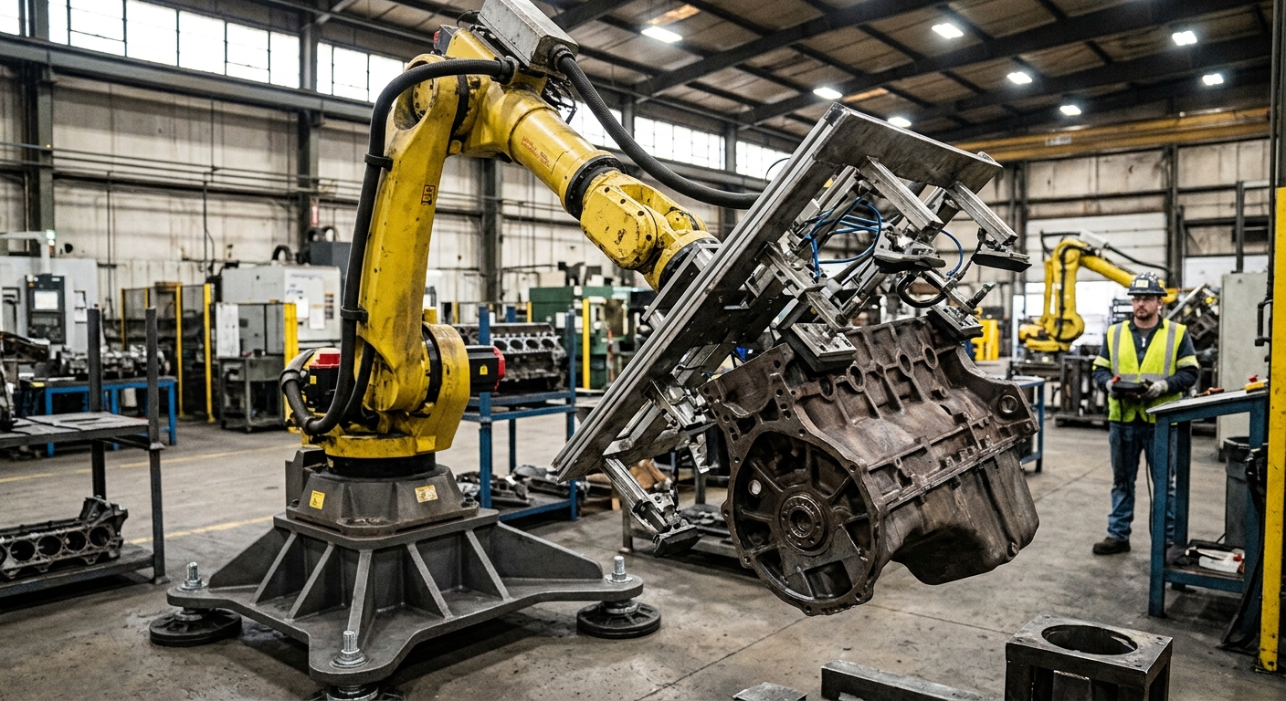

Industrial robots can handle large parts with a changing center of gravity when engineers account for shifting center gravity throughout the handling process. A part may remain within the robot’s rated payload while creating excessive wrist loading as its mass distribution changes. Managing shifting center gravity requires engineers to consider more than the total weight of the workpiece.
This situation occurs when components are rotated, repositioned, partially supported, or modified during production. Large metal panels, structural assemblies, molds, and irregular components can place different demands on a robot as their orientation or physical configuration changes. These variations affect joint loading, gripping stability, and the forces generated during acceleration.
The practical solution combines accurate load calculations, suitable end effectors, controlled motion profiles, and process validation. Engineers must identify the most demanding handling conditions before selecting equipment. This article explains how changing load distribution affects robot performance, which technical parameters require verification, and how to develop a handling process that maintains control throughout production.
How shifting center gravity affects robotic handling
Understanding shifting center gravity begins with identifying the effective location of a component’s weight and how it affects mechanical loading. Its position relative to the robot wrist determines part of the mechanical loading transmitted through the end effector. A changing load distribution can therefore alter the demands placed on the robot.
Understanding load distribution
When a rigid part rotates without changing shape or mass distribution, its center of gravity remains fixed relative to the part. However, its position relative to the robot base and gravity changes. This can produce different gravitational torques at the robot joints.
When the center of gravity actually moves
The center of gravity moves relative to the workpiece when material is removed, liquid shifts, components slide, or attached equipment changes position. Engineers must distinguish these situations from ordinary rotation because they require different load calculations and handling strategies.
Why robot payload ratings are not enough
Shifting center gravity can create additional mechanical demands even when a workpiece remains within the robot’s rated payload capacity. Manufacturers also specify permissible center-of-gravity locations, inertia, and other loading conditions that must be respected.
Wrist torque and load distance
A heavy component positioned far from the wrist creates a different moment than the same mass positioned close to the mounting flange. This relationship matters when long grippers, extended brackets, or asymmetric workpieces are involved.
The assessment must include the combined mass of the workpiece, gripper, adapters, and attached equipment. The article on robot tooling compatibility and load assessment explains why payload, center of gravity, and inertia must be evaluated together.
Inertia during acceleration
Mass distribution also affects rotational inertia. A long component may require greater joint torque during acceleration or braking than a compact component of equal mass. Engineers should compare the intended motion profiles with the manufacturer’s permissible dynamic loading conditions.
How gripping systems compensate for changing loads
Gripper design plays a central role in managing shifting center gravity because it determines how forces transfer from the workpiece to the robot. For large components, the gripping arrangement must accommodate the expected load cases without allowing unwanted movement, deformation, or loss of retention.
Positioning the gripping points
Engineers can position gripping points around the expected load distribution to reduce unnecessary bending and torque. Multiple contact points may improve support, provided their arrangement does not introduce excessive stress into the component.
Using adjustable gripping mechanisms
Some applications benefit from adjustable clamps, synchronized gripping elements, or purpose-built support frames. These arrangements can accommodate different part geometries, although their operation must be coordinated with the robot and verified for every intended configuration.
Vacuum systems require particular attention to surface condition, available holding force, acceleration, and failure behavior. Mechanical clamps also need suitable contact geometry and retention capacity. Neither gripping method should be selected using component weight alone.
How motion planning manages shifting center gravity
Motion planning must account for shifting center gravity because acceleration, braking, and changing orientations affect the forces acting on the robot. Even when the static load is acceptable, aggressive acceleration or an unfavorable orientation may exceed permissible loading conditions or compromise gripping stability.
Controlling acceleration and deceleration
Motion profiles should reflect the most demanding load configuration. Lower acceleration may reduce dynamic loading, but the permitted values depend on the robot model, load properties, and programmed movement. Manufacturer load calculations should guide these decisions.
Managing orientation changes
Large components may require rotation to access processing stations or assembly fixtures. Each orientation should be checked for joint loading, gripping forces, clearance, and reachability. Particular attention is needed when the component extends substantially beyond the robot wrist.
Collision analysis must include the complete occupied space of the workpiece. The article on preventing interference in multi-robot cells provides additional guidance on evaluating moving components, shared spaces, and recovery paths.
When external support becomes necessary
Not every large component should remain fully suspended throughout production. External supports can reduce the load carried by the robot, although the transfer of forces between the robot and support equipment must be engineered carefully.
Fixtures and positioners
Fixed supports, rotary positioners, and controlled lifting devices can help manage large or asymmetric components. Their mechanical interfaces must accommodate the intended movement without imposing unexpected forces on the robot or workpiece.
Coordinating multiple handling devices
When two robots or a robot and lifting device share a component, their movements must be coordinated. Differences in position or timing can introduce internal forces. Suitable control arrangements and load-sharing verification are therefore necessary.
How to evaluate a changing load before production
Engineering validation should examine the complete process rather than a single lifting position. The following eight checks provide a practical framework for reviewing the proposed robotic handling application.
- Determine total mass: Include the workpiece, gripping equipment, adapters, and other carried components.
- Identify load configurations: Record changes caused by material removal, moving contents, or repositioned assemblies.
- Calculate center-of-gravity locations: Establish the relevant positions for each distinct mass configuration.
- Verify wrist loading: Compare load distance and moments with the manufacturer’s permitted limits.
- Check inertia: Evaluate the load’s mass distribution against the robot’s applicable inertia limits.
- Assess gripping forces: Confirm retention capacity for the expected orientations and accelerations.
- Simulate complete movements: Review joint positions, clearances, orientation changes, and motion profiles.
- Validate actual operation: Test representative configurations using documented acceptance criteria and controlled procedures.
These checks should be repeated when tooling, workpiece geometry, processing stages, or motion parameters change. A previously acceptable load model may no longer describe the installed application accurately.
What sensors and controls can detect load changes?
Sensor systems can provide information about gripping conditions, part position, or forces acting on the handling equipment. Their usefulness depends on the measurement method, controller capabilities, and how the information is incorporated into the process.
Force and torque monitoring
Suitable force and torque sensors may help detect unexpected loading or contact conditions. However, sensor readings do not automatically identify the exact center of gravity. Estimating load distribution requires an appropriate measurement model and known operating conditions.
Controller load configuration
Some robot controllers support defined load data or application-specific load identification functions. Where supported, engineers can configure and validate different load cases according to the manufacturer’s instructions. Changes between configurations must correspond to actual process conditions.
How safety requirements influence large-part handling
Changing loads can introduce hazards associated with dropped components, unexpected movement, excessive mechanical loading, or unstable support conditions. The application risk assessment must consider normal production, foreseeable faults, maintenance, and recovery operations.
The OSHA technical guidance on industrial robot safety provides information about robotic hazards and safeguarding considerations. Applicable standards, manufacturer instructions, and local regulatory requirements must also be considered when designing the complete installation.
Safety measures may include engineered retention systems, protective guarding, monitored operating conditions, and controlled recovery procedures. The appropriate measures depend on the application risk assessment. Ordinary process monitoring should not be assumed to provide a validated safety function.
How to select a suitable robotic handling solution
Selecting a robot for applications involving shifting center gravity requires evaluating the most demanding load configurations rather than relying on nominal workpiece mass. Engineers should compare payload, reach, permissible center-of-gravity location, inertia, tooling dimensions, and the required production sequence.
For oversized components, the cell layout may determine whether an industrial robot can operate within acceptable limits. The article on validating the working envelope of large robotic cells discusses how reach, equipment geometry, and collision analysis influence practical robot operation.
When evaluating an application with changing load distribution, contact Robotic Hi-Tech Solutions with the workpiece dimensions, estimated mass properties, gripping concept, and process sequence. These details provide a starting point for assessing robot selection, tooling, and integration requirements.
FAQ
Can a robot handle a part whose center of gravity changes?
Yes, provided every relevant load configuration remains within the robot’s permitted operating limits and the gripping system maintains secure retention.
Does rotating a rigid part change its center of gravity?
Not relative to the part itself. Rotation changes its orientation relative to gravity and the robot, which can change the gravitational torques acting on individual joints.
Can a robot lift a part that is lighter than its rated payload?
Not necessarily. Center-of-gravity distance, inertia, tooling mass, and motion conditions may make the application unsuitable despite an acceptable total weight.
Can robot software automatically compensate for changing loads?
Some controllers support load configuration or identification functions. Their capabilities vary, and any compensation must be configured and validated for the intended application.
How does an extended gripper affect robot loading?
An extended gripper increases the distance between the wrist and the carried mass. Depending on the configuration, this can increase wrist moments and inertia.
Are multiple robots suitable for handling one large component?
They can be, but coordinated motion, load sharing, gripping stability, and fault recovery require specific engineering and validation.
Can sensors measure a changing center of gravity?
Appropriate measurements can support estimation of load distribution. However, accurate results require a suitable model, calibration, and controlled measurement conditions.
When should the load assessment be repeated?
Repeat the assessment whenever changes to the workpiece, tooling, gripping positions, process sequence, or motion profile could alter the forces acting on the robot. “`