English
 Italiano
 Українська
 Русский
 Español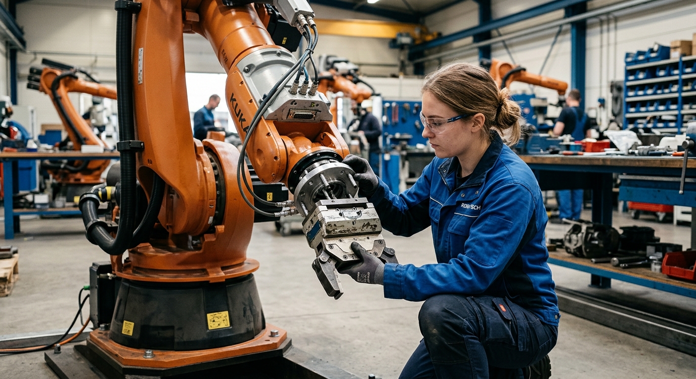

A refurbished industrial robot can support a modern end effector only when the complete tool installation falls within the robot’s mechanical, electrical, control, and application requirements. Checking refurbished robot tooling therefore requires more than confirming that the end effector can be attached to the wrist. Payload, center of gravity, inertia, flange geometry, utilities, communication interfaces, and controller capability all need to be reviewed.
The evaluation of refurbished robot tooling should begin with documentation for the exact robot model and controller configuration. The proposed end effector should then be assessed as an assembled system, including adapters, tool changers, valves, sensors, cables, hoses, and any workpiece carried by the tool. A nominal payload value alone does not establish compatibility.
The objective is to identify incompatibilities before purchasing or installing the end effector. A suitable refurbished robot should provide the required mechanical capacity and controller functions while allowing the complete cell to be engineered and validated for its intended application.
1. Start with the exact robot configuration.
Identify the manipulator and controller.
Record the robot model, variant, controller generation, installed software options, wrist configuration, and available technical documentation before evaluating refurbished robot tooling.
Review the refurbishment documentation.
Confirm what was inspected, repaired, replaced, calibrated, and tested during refurbishment. Particular attention should be given to the wrist, flange, cabling, connectors, brakes, and mechanical condition because these components directly affect tooling integration. The article on robot acceptance testing for refurbished robots explains how to verify mechanical condition, joints, cable routing, connectors, controller functions, and the documented scope of refurbishment before the robot is approved for a new application.
2. Check the refurbished robot tooling payload.
Calculate the complete installed load.
The payload assessment for refurbished robot tooling should include every component carried by the wrist. This normally means the end effector itself plus brackets, adapter plates, tool changers, sensors, valves, cable components, and any workpiece or material supported by the robot during operation.
Do not compare only the end effector’s catalog mass with the robot’s nominal payload. When evaluating refurbished robot tooling, the relevant load is the complete operating assembly. The manufacturer’s documentation for the exact robot should be used to determine the applicable payload conditions and permitted load data.
Consider changing loads.
Some applications change the wrist load during the cycle. A gripper may pick up a component, while an extrusion or dispensing system may carry equipment whose operating condition changes. The assessment should cover the relevant operating states rather than only the empty tool.
3. Verify center of gravity and inertia.
Payload capacity is not the only limit.
Two end effectors with the same mass can load refurbished robot tooling differently. A compact tool positioned close to the wrist does not create the same mechanical loading as a long assembly that places its mass farther from the mounting flange.
The center of gravity therefore needs to be checked against the robot manufacturer’s permitted load diagrams or calculation method. The article on selecting a robot according to tool payload, center of gravity, inertia, reach, and controller requirements provides a practical example of how these parameters should be evaluated together.
Check dynamic load data.
Tool inertia should also be considered where required by the manufacturer. Inertia affects how the wrist responds during acceleration, deceleration, and changes in orientation. Tool dimensions, mass distribution, programmed speed, and motion profile can therefore influence whether the proposed installation remains within permitted operating conditions.
Use manufacturer-approved load calculation tools or documentation when available. Avoid estimating acceptable center-of-gravity or inertia limits from another robot model, even when its nominal payload appears similar.
4. Confirm the mechanical flange interface
Check dimensions rather than appearance.
Mechanical compatibility is another required check for refurbished robot tooling. Compare the robot wrist interface with the mounting pattern required by the end effector or tool changer. Verify bolt pattern, pilot diameter, orientation, mounting surface, fastener requirements, and any adapter plate that will be needed.
ISO 9409-1 defines principal dimensions, designation, and marking for circular mechanical interface plates used with manipulating industrial robots. The standard supports interchangeability of mechanical interfaces, but it does not establish the load-carrying capacity of a particular robot and end-effector combination.
Evaluate adapter plates
An adapter can solve a geometric mismatch, but it also adds mass and changes the tool’s position relative to the wrist. For refurbished robot tooling, its contribution must therefore be included when calculating total payload, center of gravity, and inertia. The adapter and fasteners also need to be engineered for the loads generated by the intended application.
5. Check electrical, pneumatic, and communication interfaces.
Identify the tool’s utility requirements.
Modern refurbished robot tooling may require electrical power, compressed air, vacuum, sensor connections, communication, or combinations of these services. Compare those requirements with the robot, controller, dress pack, and surrounding cell infrastructure rather than assuming the original wrist connections can support the new device.
Review controller communication.
Some tools can be controlled with conventional digital inputs and outputs. Others rely on a communication interface, dedicated controller, PLC, or external process equipment. Verify which interfaces are available on the installed robot controller and whether the required hardware and software options are present.
An older controller does not automatically prevent refurbished robot tooling from being integrated with modern equipment. However, additional interface hardware or a different control architecture may be required when the tool uses communication methods that the original controller does not directly support.
6. Evaluate cable routing and physical movement
Check the complete robot envelope.
Refurbished robot tooling must be evaluated through the actual robot poses required by the process. Long tools, side-mounted equipment, connectors, cable loops, and hoses can interfere with the robot arm, workpiece, fixtures, guarding, or surrounding equipment even when the robot itself has sufficient reach.
Routing should allow the wrist to move through the required orientations without excessive bending, stretching, twisting, crushing, or snagging of cables and hoses. Tool geometry can also reduce usable access to the workpiece, so reach should be assessed with the end effector installed rather than from the bare robot envelope alone.
7. Use an eight-point compatibility check.
Before approving refurbished robot tooling, document the following eight items for the exact robot and proposed end-effector configuration:
- Confirm the exact robot model, variant, controller, software configuration, and available manufacturer documentation.
- Calculate the complete wrist load, including the tool, adapters, tool changer, sensors, cables, accessories, and carried workpiece where applicable.
- Verify the assembled tool’s center of gravity against the permitted load conditions for the robot.
- Check tool inertia or other dynamic load parameters required by the robot manufacturer’s documentation.
- Compare the wrist flange geometry with the end-effector interface and document any required adapter.
- List electrical, pneumatic, vacuum, and other utility requirements and confirm how each service will be supplied.
- Verify the required I/O, communication interfaces, controller options, and external control equipment.
- Review cable routing, collision clearance, tool orientation, working envelope, and application-specific test requirements.
Keep these findings with the robot configuration and integration records. This provides a documented basis for determining what has been verified and what still requires engineering or testing.
8. Test the complete configuration before production.
Separate compatibility from process performance.
Refurbished robot tooling that satisfies the robot’s load and interface requirements has passed only part of the evaluation. The complete configuration still needs application-relevant testing. A gripper must handle its intended workpiece, while a spindle, dispenser, welding tool, or extrusion head introduces different process loads and control requirements.
Review safety after the tooling change.
Changing the end effector can alter the robot’s physical envelope, hazards, stopping behavior, access conditions, and interactions with other equipment. The safety assessment should therefore address the complete integrated machine or cell rather than treating the robot arm as an isolated component.
Testing should use defined conditions and acceptance criteria. Record the installed tool configuration, load data, operating modes, relevant motion tests, alarms, interface behavior, and unresolved limitations. Do not use a successful unloaded movement as proof that the robot is ready for the intended process.
9. Make the decision from documented compatibility
A refurbished robot can be a suitable platform for a modern end effector when its mechanical capacity, controller architecture, utilities, and physical condition match the requirements of the complete tooling system. Refurbished robot tooling should therefore be approved from documented compatibility rather than robot age alone. A complete refurbished robot tooling assessment should also record any limits that affect the intended application.
If documentation or configuration details are incomplete, obtain the missing information before final tool selection. Robotic Hi-Tech Solutions can be contacted for a technical discussion using the robot model, controller information, proposed end effector, load data, and intended application as the basis for the assessment.
FAQ
Can a refurbished robot use a new end effector?
Yes. Refurbished robot tooling can include modern end effectors when the robot’s permitted loads, mechanical interface, controller, utilities, motion requirements, and complete cell design are compatible with the proposed configuration.
Is matching the robot payload enough?
No. Total mass is only one parameter. Center of gravity, inertia, mounting geometry, dynamic conditions, utilities, and application requirements can also determine whether the tooling is acceptable.
Can an adapter plate connect different flange patterns?
An engineered adapter may provide the required mechanical interface. Its mass and geometry must be included in the payload, center-of-gravity, and inertia assessment.
Does an older controller prevent modern tooling integration?
Not necessarily. Compatibility depends on the tool’s required signals, communication method, installed controller options, and whether external interface hardware can be integrated appropriately.
Should cables and hoses count as part of the tooling assessment?
Yes. Their mass, routing, movement, connection requirements, and possible interference should be considered when evaluating the complete installation.
Does a standardized flange guarantee end-effector compatibility?
No. A compatible mechanical interface does not establish payload, center-of-gravity, inertia, electrical, control, or process compatibility.
Should the robot be tested with the actual tool?
Application-relevant testing should use the intended configuration where practical. If substitute equipment is used, the differences and resulting limitations of the test should be documented.
Can a successful motion test prove that the integration is safe?
No. Motion testing can verify selected functional conditions, but safety requires assessment and validation of the complete integrated application, including tooling, safeguards, operating modes, interfaces, and foreseeable hazards.