English
 Italiano
 Українська
 Русский
 Español
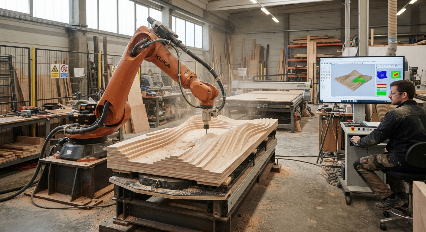

Fabrication constraints should influence computational architecture from the first design decisions, not after a complex geometry has been approved. Material behavior, machine reach, tool access, and assembly requirements determine whether a digital model can become a physical building component. Ignoring these conditions can lead to redesign, additional machining operations, or parts that cannot be produced as intended.
Computational design allows architects to generate and modify geometry through parameters, algorithms, and defined relationships. However, a mathematically valid surface is not necessarily suitable for robotic fabrication. A curved panel may exceed the available machine envelope, while a detailed connection may be inaccessible to the cutting tool.
The practical approach is to incorporate fabrication constraints into the parametric model. Designers can establish limits for dimensions, curvature, material thickness, and manufacturing access before exploring alternatives. This article explains how those limits affect geometry, robotic programming, fabrication planning, and assembly. It also examines how architects and fabrication specialists can evaluate design options without unnecessarily restricting architectural expression.
Why fabrication constraints belong in computational architecture
Connecting digital geometry with production
A computational model describes geometry and relationships between design elements. Fabrication introduces physical conditions that the model must respect. These include available equipment, material properties, positioning accuracy, and the sequence of manufacturing operations.
Introducing fabrication constraints early allows the design system to reject unsuitable configurations or identify them for further evaluation. This reduces dependence on manual corrections after geometry has been finalized.
Understanding the limits of automated design
Parametric software can evaluate geometric rules, but it does not automatically establish manufacturing feasibility. That requires reliable information about the intended production process. Designers must distinguish between constraints that software can calculate and conditions requiring physical testing.
How material properties influence geometric decisions
Material dimensions and behavior
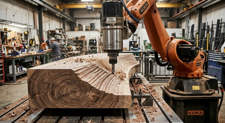
Material selection affects the geometry that can be manufactured. Sheet thickness, stock dimensions, grain direction, and forming behavior may restrict certain shapes. For example, a curved timber component may require a different construction method from a similarly shaped foam component.
Design parameters should reflect the selected material and process. Minimum feature dimensions, machining allowances, and allowable deformation must come from appropriate material data, engineering calculations, or validated fabrication tests.
Accounting for manufacturing variation
Physical materials do not always match their nominal dimensions. Moisture, temperature, manufacturing tolerances, and handling can influence the finished component. Computational models should accommodate relevant variation rather than assuming that every fabricated part exactly matches its digital representation. These fabrication constraints are particularly relevant when separate components must fit together.
How robotic reach and tool access affect architectural geometry
Evaluating the working envelope
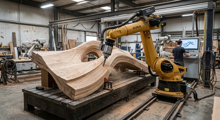
An industrial robot has a defined range of motion, but reach alone does not establish whether a machining operation is possible. Tool orientation, joint limits, fixtures, and nearby equipment also affect accessibility.
For architectural components, designers should evaluate representative tool positions throughout the proposed geometry. The relationship between the digital model and machine programming is explored further in technical articles on robotic fabrication and programming.
Preventing inaccessible machining regions
Deep cavities, narrow openings, and steep surface transitions may prevent a cutting tool from reaching the required orientation. A robot may reach a point geometrically while its spindle or supporting structure collides with the workpiece.
Changing local geometry, adjusting the component orientation, or selecting another manufacturing sequence can improve access. Each option should be checked through robot simulation and, when appropriate, physical trials.
How fabrication methods shape parametric design rules
Designing for subtractive manufacturing
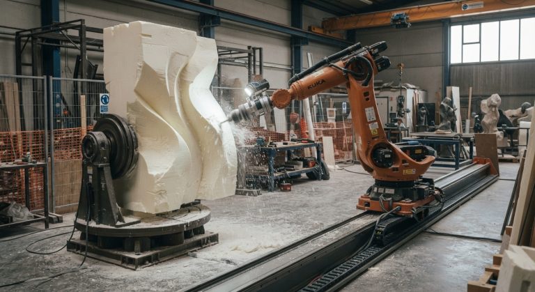
Robotic milling removes material from an initial workpiece. Tool diameter, cutting direction, workholding, and finishing requirements influence the resulting geometry. Internal corners, for example, cannot be produced with a conventional cylindrical milling tool as perfectly sharp intersections.
Architects can account for these fabrication constraints through minimum radii, accessible machining directions, and suitable stock allowances. Related applications are covered in the robotic milling articles.
Considering additive manufacturing
Large-format additive manufacturing introduces different constraints. Deposition paths, layer support, material flow, and process stability influence the forms that can be produced. Overhangs and thin features may require additional support or changes to the printing strategy.
Computational rules should therefore reflect the actual deposition system rather than assumptions based only on the final geometry. Fabrication constraints associated with material deposition should be evaluated against the intended process and equipment.
Why tolerances and assembly must influence the model
Defining realistic dimensional requirements
Fabrication tolerances describe permitted differences between specified and manufactured dimensions. Their selection depends on component function, material, production method, and inspection capability.
Applying unnecessarily restrictive tolerances can complicate production. Conversely, excessive variation may prevent components from fitting together. Designers should assign tolerances according to functional requirements instead of applying one value throughout the project.
Designing connections before fabrication
Architectural components require practical connections, lifting provisions, and installation sequences. A geometrically continuous surface may need to be divided into sections for manufacturing or transportation.
Connection locations should account for structural requirements, tool access, alignment, and installation. These fabrication constraints can become parameters within the computational model, allowing designers to evaluate alternative divisions.
How to validate fabrication constraints before production
Combining simulation and physical testing
Digital simulation can identify unreachable positions, potential collisions, and unsuitable tool orientations. However, geometric simulation alone cannot establish cutting forces, surface quality, or actual dimensional accuracy.
Representative test pieces help evaluate these conditions. A useful test should include difficult geometric features, relevant materials, and the intended manufacturing method. Test results can indicate whether the initial fabrication constraints need adjustment before production.
Including safety in fabrication planning
Robot cell layouts must account for equipment movement, workpiece handling, maintenance access, and personnel protection. The OSHA technical guidance on industrial robot system safety describes hazards, risk assessments, and safeguarding considerations for robotic applications.
Safety requirements should inform the production layout before the equipment configuration is finalized. A successful simulation does not replace a documented risk assessment or validation of protective measures.
Practical checklist for fabrication-aware computational design
Before approving a parametric architectural component, designers and fabrication specialists can use the following checks to identify fabrication constraints, production restrictions, and unresolved technical decisions.
- Confirm material availability: Compare proposed component dimensions with available stock sizes and material specifications.
- Check machine capacity: Verify the work envelope, payload requirements, and physical dimensions of the complete fabrication setup.
- Evaluate tool accessibility: Test representative tool orientations and identify potential collisions with fixtures or workpieces.
- Define geometric limits: Establish suitable feature dimensions, curvature restrictions, and machining allowances for the selected process.
- Review dimensional tolerances: Assign requirements according to component function, assembly needs, and available inspection methods.
- Plan component segmentation: Examine manufacturing dimensions, transportation restrictions, lifting arrangements, and connection locations.
- Validate representative geometry: Produce test pieces containing the most demanding features before committing to full production.
- Document production assumptions: Record machine configurations, material choices, inspection criteria, and approved design parameters.
How early coordination improves design decisions
Establishing a shared design workflow
Architects, engineers, robotic programmers, and fabrication specialists should agree on production assumptions before developing detailed geometry. This includes identifying which parameters are fixed and which can change during design development.
For projects involving complex architectural surfaces, the robotic art and architecture resources provide additional context on the relationship between geometric design and robotic production.
A shared workflow also needs clear revision procedures. Changes to material thickness, tool dimensions, or component orientation may affect several dependent parameters. Recording those relationships helps teams evaluate modifications without losing track of their manufacturing consequences.
For projects requiring an assessment of fabrication constraints, robotic machining, or manufacturing feasibility, the Robotic Hi-Tech Solutions contact page provides a way to discuss the proposed geometry, materials, and production requirements.
Frequently asked questions
What are fabrication constraints in computational architecture?
They are manufacturing and assembly conditions that influence digital design decisions. Examples include material dimensions, machine reach, tool accessibility, tolerances, and component handling requirements.
Should fabrication constraints limit architectural creativity?
They establish practical boundaries rather than prescribing a single design. Architects can explore multiple geometries within those boundaries and compare the manufacturing implications of different alternatives.
Can parametric software automatically verify fabrication feasibility?
Software can evaluate programmed geometric rules and support manufacturing simulations. Complete feasibility assessment also requires process knowledge, equipment data, and physical validation where necessary.
Why is robotic reach different from tool accessibility?
Reach describes the positions a robot can potentially attain. Tool accessibility also depends on orientation, joint configuration, collisions, fixtures, and the physical dimensions of the end effector.
How do fabrication tolerances affect computational models?
Tolerances define acceptable dimensional variation. They influence connection geometry, component clearances, inspection requirements, and the ability to assemble manufactured parts.
When should architectural components be divided into smaller parts?
Segmentation should be considered when manufacturing capacity, transportation, installation, or structural requirements make a single component impractical. Connection design must also be evaluated.
Can robotic simulation replace fabrication testing?
No. Simulation can identify geometric and motion-related problems, but physical testing may be needed to evaluate material behavior, cutting performance, surface finish, and dimensional accuracy.
What information should architects provide to robotic fabrication specialists?
Useful information includes the digital geometry, material specifications, dimensional requirements, expected surface quality, connection details, and anticipated production quantities. These details support an initial feasibility assessment.