English
 Italiano
 Українська
 Русский
 Español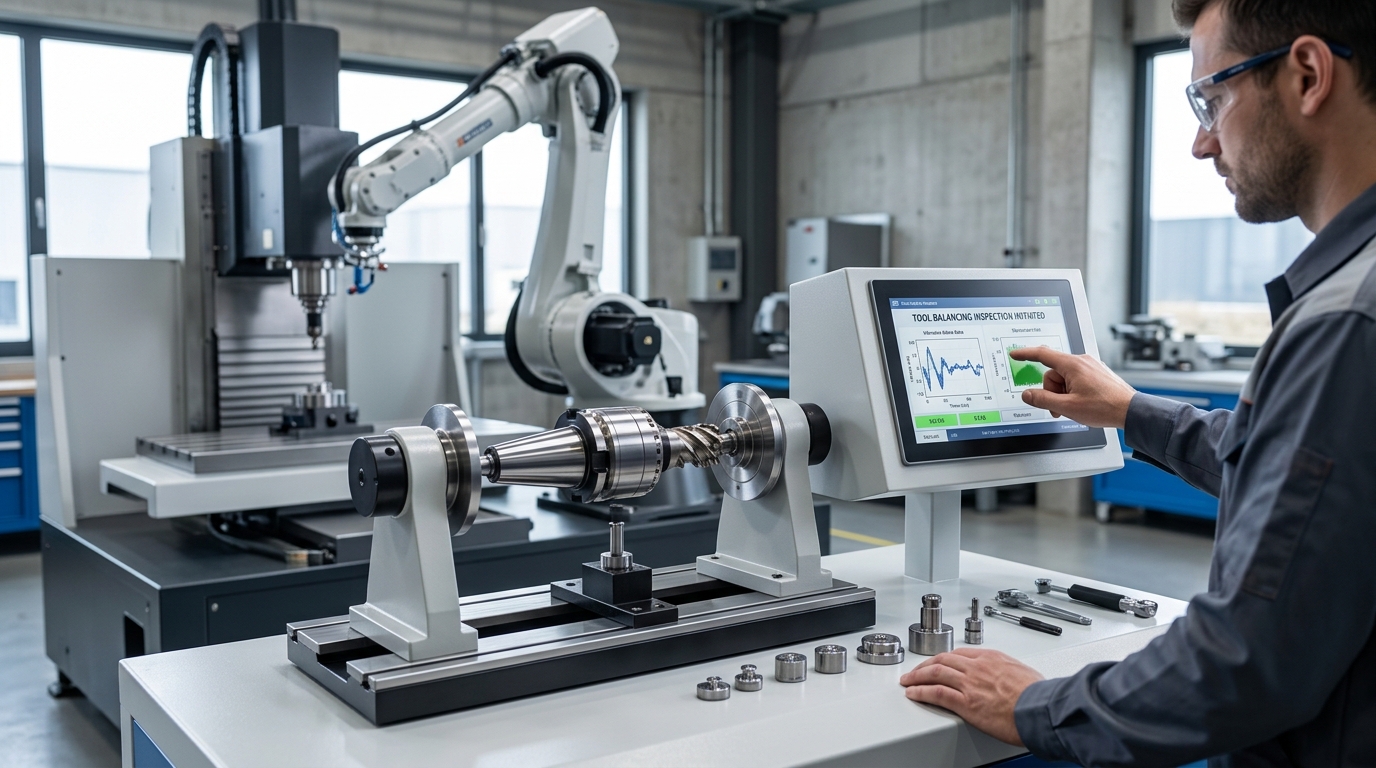

Tool balancing matters in high-speed robotic milling because a small uneven distribution of mass can generate vibration as the tool assembly rotates. That vibration may affect the spindle, tool holder, cutter, robot structure, surface finish, and consistency of the machining process. The effect becomes more relevant as rotational speed increases.
Effective tool balancing considers the complete rotating assembly, not only the cutting tool. The cutter, collet, clamping nut, tool holder, adapters, and any removable components can influence the final balance condition. A component that was balanced separately does not guarantee that the assembled system will remain within the required tolerance.
This article explains how tool balancing affects robotic milling, how it differs from runout, which warning signs deserve investigation, and how to evaluate a tool assembly before high-speed operation. The correct acceptance limit must come from the spindle manufacturer, tool-system supplier, balancing procedure, and actual operating conditions.
What Does Tool Balancing Mean?
Understanding unbalance in a rotating assembly
Unbalance exists when the mass of a rotating tool assembly is not distributed evenly around its axis of rotation. As the spindle turns, the uneven mass produces a rotating centrifugal force. The force changes direction continuously and can excite vibration in the spindle, robot wrist, tooling, fixture, or workpiece.
Residual unbalance is the amount that remains after correction. Balancing does not create a perfectly uniform assembly. Instead, the process measures the existing condition and removes or adds material or adjusts designated balancing elements until the assembly satisfies an established permissible limit.
Why the complete assembly must be evaluated
A cutter and holder may each have acceptable individual balance conditions but behave differently when assembled. Collet position, clamping orientation, assembly tolerances, contamination, removable screws, and tool replacement can change how mass is distributed. For this reason, high-speed applications often require assessment of the operational assembly.
Why Tool Balancing Becomes More Important at High Speed
Rotational speed increases unbalance forces
The centrifugal force caused by a given unbalance rises with the square of rotational speed. Doubling speed therefore produces four times the force from the same unbalance condition. This physical relationship explains why an assembly that appears acceptable at moderate speed may cause significant vibration at a higher operating speed.
Operating speed alone does not determine the required balance condition. Assembly mass, tool diameter, tool length, spindle design, holder interface, robot configuration, and structural resonance also matter. A balance grade should never be selected without considering the relevant tool and spindle documentation.
How Unbalance Affects a Robotic Milling Cell
Vibration can travel through the robot structure.
An industrial robot is less rigid than a conventional machine-tool structure, and its stiffness changes with its pose. Vibration generated at the spindle may pass through the wrist, joints, base, fixture, and workpiece. Certain robot positions or spindle speeds can amplify the response if they approach a structural resonance.
Tool balancing cannot correct low robot stiffness, excessive tool overhang, weak fixturing, unsuitable cutting parameters, or an unstable spindle mount. It removes one potential source of vibration. This guide to choosing tool holders for high-speed robotic milling explains how holder selection, runout, clamping, and tool projection also affect machining stability.
What Machining Problems Can Unbalance Cause?
Surface quality and dimensional consistency
Vibration can leave periodic marks, waviness, or an inconsistent texture on a machined surface. It may also change the way the cutting edge enters the material. The resulting dimensional effect depends on the vibration amplitude, tool path, material, cutter geometry, robot pose, feed rate, and depth of cut.
Unbalance should not automatically be blamed for every surface defect. Similar symptoms can result from tool runout, chatter, damaged bearings, poor clamping, incorrect feeds and speeds, worn cutting edges, or movement of the workpiece. Diagnosis should compare evidence rather than rely on appearance alone.
Tool Balancing Versus Tool Runout
Different conditions requiring different measurements
Tool balancing concerns the distribution of mass around the rotational axis. Runout describes how far a rotating surface or cutting edge deviates from its intended axis. An assembly can have low residual unbalance but excessive runout, or acceptable runout but an unsuitable balance condition.
Runout is commonly checked with a suitable indicator or dedicated measuring system at a defined location. Balance is evaluated on equipment capable of determining residual unbalance and its correction plane. This guide to spindle runout in robotic milling explains how runout affects cutting loads, surface finish, and troubleshooting. Both conditions may need to be measured before changing robot programming or cutting parameters.
Eight Checks Before High-Speed Robotic Milling
The following checks provide a practical inspection sequence. Acceptance criteria must remain specific to the spindle, holder, cutter, balancing equipment, and intended maximum speed.
- Confirm the speed limits: Check the rated maximum speed of the spindle, holder, collet, cutter, adapters, and retention components. The lowest applicable limit governs the assembly.
- Inspect every interface: Look for dirt, chips, corrosion, burrs, fretting, or impact damage on the spindle taper, holder, collet, nut, cutter shank, and contact faces.
- Define the operational assembly: Record every component that will rotate during machining, including screws, balancing rings, coolant hardware, and removable accessories.
- Control assembly orientation: Follow the supplier’s assembly and tightening instructions. If orientation influences repeatability, mark and document the approved position.
- Measure tool runout: Check runout at a defined point and compare it with the requirements of the tool, holder, and process. Do not treat a balance result as a runout measurement.
- Balance at the correct configuration: Use the same cutter projection, collet, nut, adapters, and other components intended for production whenever the procedure requires assembly balancing.
- Record the balance result: Document the assembly identity, residual unbalance, correction method, measurement planes, date, operator, and permitted operating condition.
- Conduct a controlled speed test: After installation, increase speed according to the approved commissioning procedure while monitoring unusual noise, vibration, temperature, and spindle alarms.
How Should the Balance Requirement Be Defined?
A notation such as a balance quality grade is incomplete when it is separated from operating speed, assembly mass, and the method used to calculate permissible residual unbalance. The requirement should state what is being balanced, its configuration, the relevant speed, the correction planes, and the applicable acceptance procedure.
ISO 16084:2017 for rotating tools and tool systems provides requirements and calculations related to permissible static and dynamic residual unbalance. It also addresses assembled and modular tool systems. Application still depends on the individual spindle, tool interface, clamping condition, and machining system.
A stricter balance target is not automatically better. Manufacturing tolerances, repeated clamping displacement, tool wear, interface condition, and measurement uncertainty limit what can be reproduced in production. Requirements should be technically justified and achievable with the available assembly and inspection process.
FAQ
Does every robotic milling tool require balancing?
The requirement depends on operating speed, assembly design, spindle instructions, process sensitivity, and supplier recommendations. High-speed assemblies generally require more careful evaluation than tools used at low rotational speeds.
Can a balanced holder be used without balancing the cutter?
Not necessarily. Adding the cutter, collet, nut, adapters, or screws changes the rotating assembly. The complete configuration may need to be measured after assembly.
Does tool balancing eliminate chatter?
No. Chatter is a self-excited vibration influenced by structural dynamics and cutting conditions. Balancing can reduce forced vibration from imbalance but cannot resolve every stability problem.
Is balance the same as concentricity?
No. Balance concerns mass distribution, while concentricity and runout concern geometric alignment. Separate measurements are required because one result does not establish the other.
Should a tool be rebalanced after replacing the cutter?
Re-evaluation may be necessary because the replacement changes the assembly. Follow the defined production procedure and the recommendations supplied with the holder, cutter, and balancing equipment.
Can contamination affect balance results?
Yes. Chips, residue, corrosion, and damaged contact surfaces can alter assembly position or mass distribution. Components should be cleaned and inspected before measurement and installation.
Can balancing compensate for a long tool overhang?
No. Balancing does not restore stiffness lost through excessive projection. Long tools may deflect or vibrate even when their residual unbalance satisfies the specified limit.
When should the spindle be inspected instead?
Investigate the spindle when abnormal vibration persists across different verified tool assemblies or is accompanied by unusual noise, temperature, runout, alarms, or changes in operating behavior.
Integrating Tool Balancing Into the Milling Process
Tool balancing should be managed as part of tooling control rather than as a one-time correction. Assembly instructions, inspection intervals, runout results, balance records, tool life, and observed vibration provide a traceable basis for deciding when an assembly can return to service.
During process development, compare results across controlled spindle speeds and robot poses. If vibration appears only in particular configurations, investigate the interaction among the tool assembly, spindle mount, robot stiffness, fixture, and cutting parameters before changing several variables at once.
For support defining a robotic milling cell, spindle configuration, or tooling validation procedure, contact Robotic Hi-Tech Solutions with the intended material, tool system, spindle range, robot model, workpiece dimensions, and required machining result. These details allow the application to be assessed against its actual operating conditions.