English
 Italiano
 Українська
 Русский
 Español

Robotic architecture connects digital design, industrial robots and physical fabrication in a single production workflow. Instead of treating the robot as equipment that enters only after the design is complete, architects and fabrication teams can use its reach, repeatability and multi-axis movement to influence geometry, material strategy and assembly from the beginning of the project.
The robot does not become the author in a human or artistic sense. It does not define the purpose of a building, evaluate spatial quality or decide which form is culturally meaningful. What it does is expose the relationship between design rules and fabrication constraints more directly than conventional drawing-based workflows.
Authorship therefore becomes distributed across the architect, computational designer, programmer, integrator, tool, material and production system. The architectural result is shaped not only by what was drawn, but by how the complete system was designed to make it.
Quick answer
- The architect defines the spatial and material intent.
- The computational model defines rules and variation.
- The robot executes physical operations within technical limits.
- The tool, fixture and material influence the final geometry.
- Testing feeds production constraints back into the design.
Robotic architecture is strongest when design and fabrication are developed as one system rather than as separate project stages.
What robotic architecture actually means
Robotic architecture refers to the use of programmable robotic systems in architectural design, prototyping, component production, construction research and full-scale fabrication. The term covers more than robotic 3D printing.
An industrial robot can be configured to:
- mill timber, foam, composites, stone or other materials;
- cut or trim non-standard components;
- deposit concrete, polymers, clay or metal;
- fold, bend or form sheets and profiles;
- place, orient or assemble individual elements;
- scan physical objects and compare them with digital models;
- coordinate tools, sensors or external axes during production.
The architectural value does not come from using a robot for its own sake. It comes from designing a process in which programmable movement makes a specific geometry, material operation or degree of variation possible.
Why robotic architecture focuses on process rather than form
Traditional architectural workflows often separate design from production. The architect defines a form, documentation is prepared and a contractor or fabricator determines how the object can be built.
Robotic fabrication reduces that separation. Tool access, robot posture, material behaviour, fixture strategy and production sequence can influence the design while it is still being developed.
A surface may change because the selected spindle cannot reach a corner without collision. A component may be divided differently because the robot working envelope is limited. A pattern may become denser or more open because the production time changes with every toolpath. An assembly system may be redesigned because the robot must approach each connection from a stable orientation.
The result is not simply a form produced by a robot. It is a form that has emerged through negotiation between design intent and fabrication logic.
How parametric design connects architecture to robotic fabrication
Parametric design allows architects to define relationships rather than draw every component independently. Dimensions, spacing, curvature, orientation and repetition can respond to variables such as structure, material, daylight, fabrication time or assembly sequence.
When the parametric model is connected to a robotic workflow, those relationships can generate:
- toolpaths;
- component positions;
- cutting or deposition sequences;
- tool orientations;
- assembly instructions;
- robot and external-axis coordination.
This creates a direct link between design changes and production data. A modification to the architectural model can update the geometry of multiple components and, when the workflow is properly built, regenerate the corresponding fabrication paths.
That flexibility is valuable, but it also creates responsibility. A geometrically valid parametric result may still be impossible to manufacture if it ignores robot kinematics, tooling, material support or process tolerances.
For a deeper examination of this relationship, see parametric design and robotic fabrication.
Where authorship exists in a robotic architecture project
| Project layer | Primary contribution | Effect on the result |
|---|---|---|
| Architectural concept | Defines spatial intent, programme, context and material ambition. | Establishes why the robotic process is relevant to the project. |
| Parametric model | Defines relationships, constraints, variation and generative rules. | Controls how the design changes across components or conditions. |
| Robotic programming | Converts geometry into executable movement and process logic. | Shapes sequence, orientation, speed, access and production feasibility. |
| Tool and end effector | Performs cutting, deposition, placement, scanning or forming. | Defines the physical action applied to the material. |
| Material system | Responds through deformation, resistance, curing, grain or surface variation. | Introduces limits and physical characteristics absent from the digital model. |
| Integration and safety | Coordinates robot, tooling, fixtures, sensors and human access. | Determines whether the process can operate reliably and safely. |
Authorship is distributed, but not anonymous. Each contributor influences a different layer of the final work. The robot performs the programmed operation; it does not independently define the architectural intention.
What materials and processes can robotic architecture use?
Robotic architecture is not tied to one fabrication method. The same type of industrial arm can support very different processes depending on the tool, programming and material system.
Subtractive fabrication
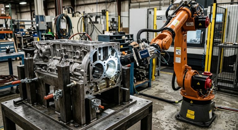
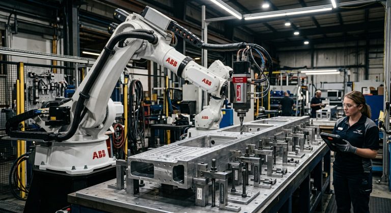
Robotic milling and cutting remove material from foam, timber, composites, plastics, stone or selected metals. The robot provides a flexible working envelope and access from multiple orientations, making it useful for large or geometrically complex components.
Process performance depends on robot stiffness, spindle selection, tool length, fixture stability, cutting forces and calibration. Complex geometry does not remove the need to control vibration, accuracy and surface quality.
Related technical guidance is available in the Milling Robots section.
Additive fabrication
Robotic deposition systems can extrude concrete, polymers, clay, composites or metal. Multi-axis movement allows deposition paths and tool orientations that may be difficult to achieve with fixed-gantry systems.
The result still depends on material preparation, feed consistency, layer bonding, deposition speed, environmental conditions and path planning. A robot arm does not solve these process variables automatically.
Explore additional applications in the 3D Printing Robots category.
Assembly and placement
Robots can position bricks, blocks, timber members, panels or customised components according to digitally generated sequences. This can support non-standard assemblies in which each element has a different position or orientation.
However, the cell must account for part tolerances, gripping, alignment, connection methods and access to each placement position.
Forming and folding
A robotic system may bend, press, fold or shape metal, composite sheets or other materials using dedicated tools and fixtures. The geometry emerges from the interaction between programmed movement, force and material response.
Scanning and adaptive fabrication
Vision systems, scanners and force sensors can compare the actual workpiece with the digital model. The robot can then adjust the process to compensate for variation, locate components or follow surfaces that are not perfectly predictable.
What changes when design and fabrication become one workflow?
Connecting architectural design directly to robotic production changes several project decisions.
Variation becomes manageable
Components do not need to be identical for the process to remain automated. A parametric system can generate related but different geometries, while the robotic workflow produces corresponding paths for each one.
Prototypes become production evidence
A prototype is no longer only a visual model. It tests reach, material behaviour, tooling, cycle time, tolerances and assembly. It becomes evidence about whether the process can scale.
Fabrication constraints enter earlier
Tool access, part support, robot posture and material limits must be considered during design. Problems that would normally appear during manufacturing become visible sooner.
Feedback can modify the design
Production data may reveal excessive tool movement, unstable postures, slow sequences or material failures. That information can be used to adjust the parametric model and regenerate the process.
Example: a non-standard facade component system
An architectural team develops a facade composed of panels with related but non-identical curvature. The parametric model generates each panel geometry, fixing points and edge conditions.
During robotic milling tests, several panels require tool orientations that place the robot close to joint limits. Instead of forcing the original geometry through an unstable machining process, the design rules are adjusted to reduce extreme curvature in those areas.
The updated model preserves the overall architectural intention while producing more stable robot paths, shorter machining time and more predictable surface quality. The fabrication process has not merely executed the design; it has provided information that improves it.
Does the robotic arm become a collaborator?
Calling the robot a collaborator can be useful if the term describes an iterative relationship between design and production. The machine reveals limits that may not be visible in the digital model, and those limits can influence subsequent design decisions.
However, the robot does not collaborate through intention or judgement. It does not understand why one spatial decision is stronger than another. It exposes consequences through movement, reach, speed, force, collision, material response and production time.
The collaboration therefore exists between people and the technical system they have created. The robot contributes predictable capabilities and measurable constraints. The designers interpret those constraints and decide how the project should respond.
What technical limits shape robotic architecture?
The most credible robotic architecture projects acknowledge the limits of the system rather than treating the robot as an unrestricted fabrication device.
- Reach: the robot must access every process point without exceeding joint limits or creating collisions.
- Payload: the selected arm must carry the tool, cables, material load and dynamic process forces.
- Stiffness: articulated robots are less rigid than dedicated machine tools, which affects machining and forming applications.
- Accuracy: robot repeatability does not automatically equal final fabrication accuracy.
- Tool orientation: complex geometry may require wrist configurations that are unstable or impossible.
- Fixtures: components must remain controlled during cutting, deposition, forming or assembly.
- Software: design geometry must be translated into paths that account for robot kinematics and process requirements.
- Cycle time: geometric freedom may create production sequences too slow for the project budget or schedule.
- Safety: industrial robots, tools and moving components require a defined risk assessment and safety architecture.
- Site conditions: laboratory workflows may not transfer directly to construction environments with variable access, weather and logistics.
A successful project does not eliminate these constraints. It incorporates them into the design system.
When robotic fabrication is the right architectural process
Robotic fabrication is most valuable when it provides a capability that conventional production methods cannot deliver efficiently or consistently.
Robotic architecture evaluation framework
- Design value: Does robotic movement enable geometry, variation or material treatment that matters to the project?
- Process: Will the robot cut, deposit, form, scan, place or assemble?
- Material: Is the material compatible with the selected robotic process?
- Scale: Can the robot and any external axes cover the required working envelope?
- Tolerance: Can the complete system achieve the required dimensional and surface quality?
- Volume: Is the project a prototype, a limited series or recurring production?
- Workflow: Can design data be converted reliably into executable robot paths?
- Integration: Are suitable tooling, fixtures, sensors, safety and technical support available?
- Economics: Does the complete cell create enough value to justify programming, testing and commissioning?
If the robot contributes only visual novelty while a simpler production method can achieve the same result more reliably, robotic fabrication may not be justified.
When variation, scale, multi-axis access, direct data-to-material production or adaptive fabrication are central to the project, the robot can become a practical architectural tool.
Can refurbished robots support architectural fabrication?
Refurbished industrial robots can be suitable for architecture, art, research and education when their technical condition, controller generation and software compatibility are verified.
They may allow studios and universities to access industrial reach and payload while allocating more of the project budget to tooling, software, fixtures, safety and material development.
The evaluation should consider:
- robot and controller condition;
- required payload and working reach;
- controller and programming compatibility;
- availability of software options;
- external-axis requirements;
- spare parts and technical support;
- transport, installation and commissioning;
- safety requirements for the intended environment.
The robot should be evaluated as one component of a complete fabrication workflow. A low acquisition cost does not compensate for incompatible software, unsuitable reach or inadequate technical support.
RHTS provides new and refurbished industrial robots that can be assessed for architectural fabrication, research and digital production applications.
Frequently asked questions
What is robotic architecture?
Robotic architecture is the use of programmable robotic systems in architectural design, prototyping, fabrication, assembly or construction research. It connects digital models with physical operations such as milling, cutting, deposition, forming, scanning or placement.
Does a robotic arm design architecture independently?
No. The robot executes programmed operations and responds to the technical system around it. Architects, designers and engineers define the intent, rules, materials, tooling and criteria used to evaluate the result.
What is the role of parametric design in robotic architecture?
Parametric design defines relationships and variables that can generate customised geometry and corresponding production data. It allows design changes to update multiple components and, when properly integrated, their robotic fabrication paths.
Which materials can be used in robotic architectural fabrication?
Depending on the tool and process, robots can work with timber, foam, composites, polymers, concrete, clay, stone, metal and other architectural materials.
Is robotic fabrication suitable only for experimental projects?
No, but many applications begin as prototypes because the process must be validated. Recurring production is possible when tooling, material behaviour, cycle time, tolerances, safety and maintenance are controlled.
Can refurbished robots be used in architecture schools and fabrication studios?
Yes, when their mechanical condition, controller, software compatibility, reach, payload and safety requirements are properly evaluated. The complete budget must also include tooling, integration, programming and support.
The robot influences architecture, but it does not become the author
Robotic architecture changes authorship because it makes the production system part of the design process. Geometry is influenced by programming, tool access, material behaviour, sequence and machine limits rather than by formal intention alone.
The robotic arm contributes precision, reach, repetition and measurable constraints. It can reveal that a geometry is difficult to fabricate, that a sequence is inefficient or that a material behaves differently from the digital model. Those findings can change the project.
But the robot does not decide why the project should exist or what the result should mean. Human authorship remains in the definition of intent, the design of the system, the interpretation of feedback and the decision to accept, modify or reject the outcome.
The strongest robotic architecture does not hide this relationship. It makes visible how code, machine and matter participate in the construction of form.
Explore further projects and technical analysis in the Robot Art & Architecture section, or contact RHTS to discuss an industrial robot platform for architectural fabrication, research or digital production.