English
 Italiano
 Українська
 Русский
 Español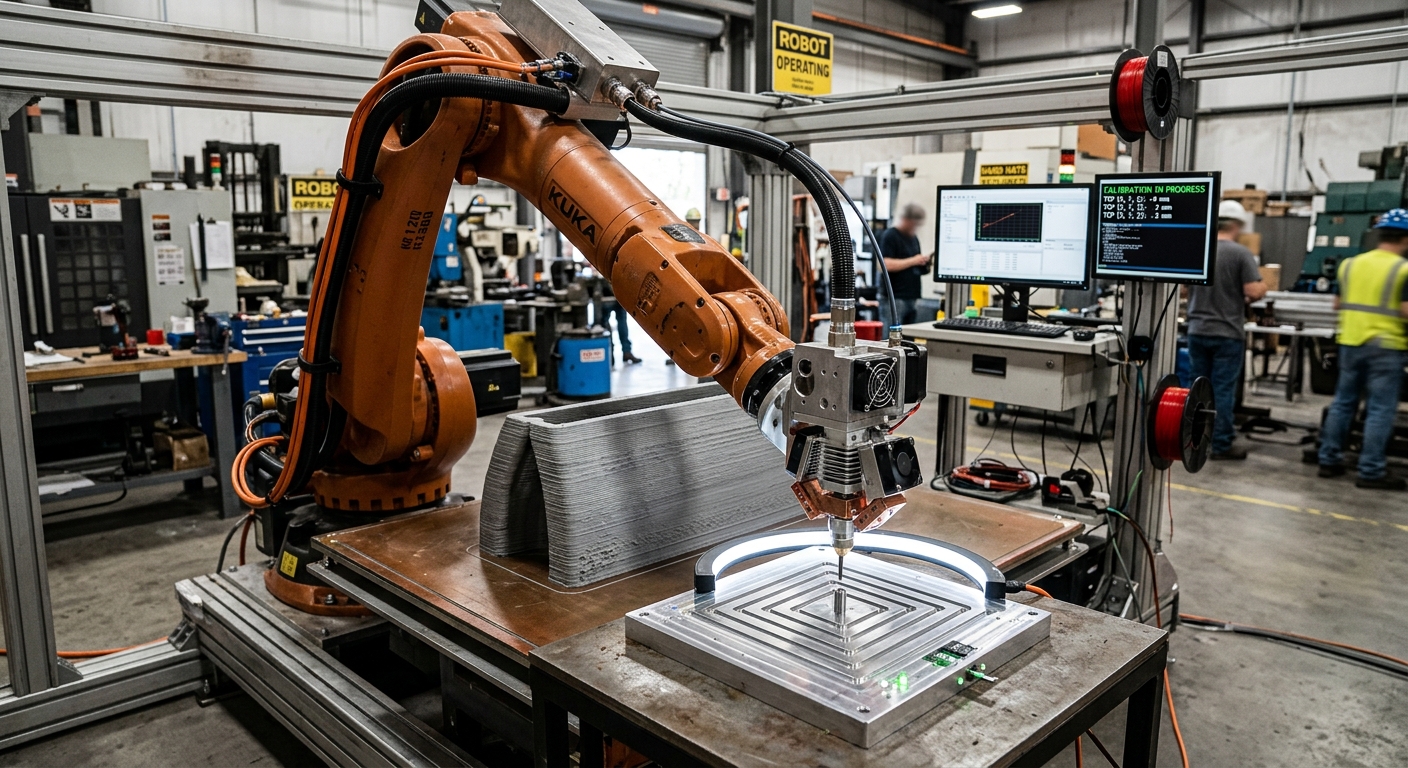

What Is Extruder TCP Calibration?
Robotic 3D printing calibration directly affects where the extruder nozzle is positioned and how accurately the robot follows the programmed deposition path. If the tool center point, or TCP, does not match the real nozzle position and orientation, the robot may execute the correct program while depositing material in the wrong location.
The effect becomes especially important when the extruder changes orientation. A TCP error that seems small in one posture can produce a larger positional deviation when the wrist rotates, which may affect layer alignment, nozzle-to-surface distance, and dimensional consistency.
This article explains how TCP errors influence robotic additive manufacturing, how to distinguish tool calibration problems from work-frame or extrusion issues, and what should be checked before production. Correct calibration does not guarantee final part accuracy, but it provides the geometric reference needed for reliable robot motion.
Why Robotic 3D Printing Calibration Changes Print Accuracy
The robot controller calculates movement using the programmed tool coordinate system. The path may be mathematically correct, but the real nozzle follows that path accurately only when its physical location relative to the flange matches the TCP stored in the controller. The same geometric principle is explained in this guide to TCP calibration errors and dimensional deviations.
Position errors shift the deposition point.
An incorrect TCP position creates an offset between the commanded point and the nozzle outlet. On a path where tool orientation remains constant, this may appear as a relatively consistent displacement. Features can be printed away from their intended location even though the robot executes the programmed path repeatedly.
Orientation changes can amplify TCP errors.
The effect becomes more complex when the robot rotates the extruder. A position error located away from the rotational reference changes direction as the tool turns. The nozzle can therefore move through an unintended arc instead of rotating around the intended deposition point.
This is one reason TCP errors matter, particularly in multi-axis additive manufacturing. A calibration that appears acceptable during a vertical test may produce noticeable deviations when the same extruder is tilted for non-planar layers, curved walls, overhang strategies, or directional deposition.
How TCP Errors Appear in a Robotic 3D Print
A TCP problem does not always produce one distinctive defect. Its visible effect depends on the direction and magnitude of the calibration error, robot posture, nozzle orientation, path geometry, layer strategy, and the relationship between the tool and the build surface.
Typical geometric symptoms
Possible symptoms include shifted deposition paths, inconsistent nozzle-to-surface distance, poor alignment where paths meet, dimensional differences after orientation changes, and unexpected transitions between segments produced with different robot postures. These symptoms should be investigated rather than automatically attributed to TCP calibration, because material flow and workpiece-frame errors can produce similar results.
A useful practical comparison is available in the FANUC and Leister robotic 3D printing case study, which discusses the relationship between robot movement, extrusion, calibration, build-platform coordinates, and printed geometry.
TCP Errors Versus Other Calibration and Process Errors
TCP calibration should not be treated as the only determinant of dimensional accuracy. The robot base, build-platform frame, robot mastering, external axes, path generation, nozzle geometry, material behavior, extrusion rate, and thermal effects can all influence the final component.
Tool errors are different from work-frame errors.
A TCP error concerns the relationship between the flange and the physical tool point. A work-frame or build-platform error instead changes the robot’s understanding of where the printing surface or component coordinate system is located. Both can shift a print, but their behavior during tool rotation is different.
Coordinate systems are fundamental to industrial robot programming and alignment. ISO 9787:2013 defines robot coordinate systems and motion nomenclature intended to support robot alignment, testing, and programming. The standard does not provide a specific robotic-extrusion calibration procedure, but it provides relevant terminology for understanding robot coordinate relationships.
How to Check Extruder TCP Calibration Before Printing
Effective robotic 3D printing calibration should confirm that the programmed tool point corresponds to the physical nozzle outlet under more than one robot orientation. Testing only one posture can hide an incorrect TCP because some errors become visible primarily when the tool rotates.
- Inspect the nozzle and mounting: confirm that the nozzle, adapter, extruder bracket, and fastening points are seated correctly and have not shifted.
- Verify the active tool data: confirm that the robot program is using the intended TCP rather than another tool definition stored in the controller.
- Check the physical reference point: use an appropriate fixed reference or calibration method to evaluate whether the nozzle reaches the same physical point.
- Test several orientations: rotate the tool around the reference while observing whether the nozzle tip remains at the intended location.
- Check nozzle orientation: verify the tool-axis direction as well as its position, especially for angled or multi-axis deposition.
- Verify the build frame separately: do not correct a platform-coordinate error by modifying otherwise valid TCP data.
- Run a controlled deposition test: compare a simple programmed geometry with the actual material path after geometric calibration.
- Record the approved configuration: document the nozzle, mounting arrangement, tool data, and calibration state so changes can be identified later.
These checks separate geometric verification from process tuning. Extrusion flow, temperature, robot speed, bead dimensions, and material behavior should be evaluated after the geometric references are known to be reliable.
When Should the Extruder TCP Be Recalibrated?
Recalibration should be considered whenever the physical relationship between the nozzle and robot flange may have changed. Examples include replacing a nozzle, removing or reinstalling the extruder, changing a mounting bracket, modifying the tool assembly, or repairing components that determine the nozzle position.
A collision or unexpected mechanical contact also justifies checking the TCP before continuing production. The tool can shift even when the robot itself remains operational. Continuing with an unverified tool definition risks reproducing a geometric offset across subsequent prints.
Routine verification can also be incorporated into the production procedure according to the application, required tolerance, tool construction, and maintenance strategy. The appropriate interval depends on the actual cell and should be based on validated process requirements rather than an arbitrary universal schedule.
Why TCP Calibration Alone Cannot Guarantee Print Accuracy
Accurate robotic 3D printing calibration establishes where the robot believes the nozzle is located, but it does not control every source of printing error. Material can shrink, deform, sag, accumulate, or respond differently as process conditions change. Nozzle distance may also be affected by an incorrectly defined build surface.
Robot repeatability is not final part accuracy.
A robot may repeatedly execute the same motion while consistently reproducing an incorrect tool or work-frame calibration. Repeatability therefore cannot demonstrate that the physical nozzle is following the intended absolute geometry. Final part accuracy must be evaluated using the deposited component and the requirements of the specific process.
Extrusion rate and robot velocity must also remain coordinated. Even with correct geometry, changes in deposition flow or motion can alter bead dimensions and cause the actual material boundary to differ from the nominal tool path. Geometric calibration and process calibration should therefore be evaluated separately and then validated together.
How TCP Calibration Supports Multi-Axis 3D Printing
In multi-axis applications, robotic 3D printing calibration becomes particularly relevant because the nozzle may continually change orientation. The programmed tool point becomes the pivot used to calculate movements while the robot changes wrist posture. An incorrect TCP can therefore generate position changes related directly to tool orientation.
This matters when printing onto curved substrates, following non-planar layers, changing deposition direction, or approaching a feature from different orientations. The more the process depends on controlled nozzle orientation, the more important it becomes to validate both the TCP position and tool-axis definition.
Simulation can verify reachability, joint motion, collisions, and programmed geometry, but the simulation model also depends on correct tool information. A digitally correct path cannot compensate for a physical extruder whose measured tool geometry differs from the data used to generate or execute that path. This relationship between digital geometry, tool orientation, robot paths, and calibration is examined further in parametric design and robotic fabrication workflows.
Frequently Asked Questions
What does TCP mean in robotic 3D printing?
TCP means tool center point. For an extrusion tool, it normally identifies the reference point associated with the nozzle that the robot controller uses to calculate programmed motion.
Can an incorrect TCP cause layer misalignment?
Yes. An incorrect TCP can shift the physical deposition point. The effect may change when the nozzle orientation changes, producing alignment errors between paths or layers.
Does calibrating the TCP also calibrate the build platform?
No. Tool calibration and build-platform or work-frame calibration define different coordinate relationships. Both need to be correct for the programmed path to correspond to the physical setup.
Should the TCP be checked after changing the nozzle?
Yes, if the replacement can change the nozzle tip position or orientation. Even nominally similar components should be verified when print accuracy depends on the physical tool point.
Can TCP calibration correct inconsistent extrusion flow?
No. TCP calibration corrects geometric tool information. Flow instability requires examination of the extrusion system, material, process parameters, feeding conditions, and their coordination with robot motion.
Can a robot be repeatable while the TCP is wrong?
Yes. A robot can repeatedly follow commands based on incorrect calibration data. In that situation, the same geometric error may be reproduced consistently.
Is one calibration posture enough to verify an extruder TCP?
Testing multiple orientations is preferable because TCP position errors often become clearer when the tool rotates around a fixed reference point.
Does every robotic 3D printing cell use the same TCP calibration method?
No. Calibration procedures depend on the robot controller, tool configuration, available calibration equipment, accuracy requirements, and integration method. Manufacturer and integrator procedures should be followed for the installed system.
Final Checks Before Production
Reliable robotic 3D printing calibration gives the controller an accurate geometric description of the nozzle relative to the robot flange. It should be verified together with nozzle orientation, build-platform coordinates, robot condition, and the physical stability of the extruder mounting before dimensional print results are evaluated.
For applications involving new extrusion tools, multi-axis deposition, changes to an existing robotic printing cell, or uncertainty about calibration strategy, teams can contact Robotic Hi-Tech Solutions to discuss the robot, extrusion equipment, geometry, and integration requirements of the application.