English
 Italiano
 Українська
 Русский
 Español

FANUC and Leister robotic 3D printing combines the movement of an anthropomorphic industrial robot with the WELDPLAST 600-i extrusion module to manufacture large plastic elements from digitally generated paths. At Politecnico di Milano, researchers developed a system that integrated these technologies to investigate modular architectural components that could be printed individually and assembled into larger configurations.
The project is relevant because it demonstrates what robotic additive manufacturing requires beyond a robot arm. The system had to coordinate digital geometry, robot movement, material extrusion, temperature, deposition rate, component design, and assembly logic.
It does not prove that any architectural structure can be printed directly or that robotic extrusion is automatically more economical or sustainable than conventional construction. It demonstrates a technical platform for researching large-scale polymer deposition and discrete architectural systems.
Quick Answer
- The FANUC robot provided programmable multi-axis movement.
- The Leister WELDPLAST 600-i supplied molten thermoplastic material through an automated extrusion process.
- The digital workflow converted architectural geometry into deposition paths and robot commands.
- The modular design strategy divided larger architectural configurations into printable elements.
- The research challenge was integrating movement, material flow, geometry, and assembly into one workable system.
The project should be understood as a robotic-fabrication case study rather than as a complete construction solution ready for unrestricted commercial use.
What Was the Politecnico di Milano Project?
The project was developed through collaboration between researchers at Politecnico di Milano and Leister specialists.
Its objective was to develop the knowledge and technical methods required to produce large architectural elements through robotic 3D printing using the Leister WELDPLAST 600-i extrusion module mounted on an anthropomorphic FANUC robot.
The research focused on:
- integrating the extrusion module mechanically with the robot;
- coordinating robot movement with thermoplastic output;
- developing digital paths for large-scale deposition;
- producing large plastic components;
- designing elements that could be assembled into broader architectural configurations;
- investigating the relationship between component geometry and fabrication strategy.
The project was associated with research into discrete architecture: an approach in which larger structures are created from separately manufactured components governed by a shared design and assembly system.
What Is the Leister WELDPLAST 600-i?
The WELDPLAST 600-i is an industrial extrusion module developed for automated plastic extrusion welding and large-format 3D printing.
Unlike a self-contained desktop printer, it is a process module intended to be integrated into a robot, machine, or larger automated installation.
Its role is to:
- receive thermoplastic material;
- heat and plasticise the material;
- generate a controlled extrusion flow;
- deposit material through a nozzle;
- communicate with the surrounding automation system;
- allow process parameters to be monitored or adjusted according to the installation.
Leister designed the WELDPLAST 600-i for automated continuous operation and publishes a maximum nominal output of approximately 6 kg of plastic per hour, depending on the configured process and material.
The actual usable deposition rate in a printed component may be lower. Print quality also depends on robot velocity, nozzle size, temperature, bead geometry, layer bonding, and the complexity of the path.
Why the Extruder Module Is Not a Complete Printer
The WELDPLAST 600-i does not independently create a robotic 3D-printing cell. It must be integrated with several additional systems.
| System Layer | Primary Function | Main Integration Requirement |
|---|---|---|
| FANUC Robot | Positions and orients the extrusion nozzle. | Suitable reach, payload, controller, mounting, and path execution. |
| WELDPLAST 600-i | Heats and extrudes thermoplastic material. | Mechanical mounting, power, material feed, temperature, and flow control. |
| Digital Design System | Defines component geometry and modular relationships. | Geometry must remain compatible with deposition and assembly constraints. |
| Path-Planning Software | Generates ordered deposition paths and tool orientations. | Paths must remain reachable, continuous, and collision-free. |
| Process Control | Coordinates robot motion with extrusion parameters. | Material flow must correspond to robot speed and path geometry. |
| Build Platform | Supports the component during deposition. | Alignment, stability, adhesion, and thermal behaviour must be controlled. |
| Safety Architecture | Controls access to hazardous robot and thermal processes. | Guarding, emergency stops, operating modes, and risk assessment. |
Key distinction: the FANUC robot provides movement, and the Leister unit provides extrusion. The printing capability exists only when both are connected through a validated material, software, control, and safety architecture.
Why an Anthropomorphic FANUC Robot Was Used
An anthropomorphic industrial robot provides six articulated axes that allow the extrusion nozzle to move and change orientation throughout a three-dimensional working envelope.
This can offer several advantages for architectural research:
- large spatial reach relative to the robot footprint;
- programmable control of nozzle position and orientation;
- access to component geometry from different directions;
- integration with external axes or repositioning systems;
- compatibility with automated tools and industrial communication;
- the possibility of producing different component geometries using one physical platform.
The robot does not remove all size constraints. Its usable build envelope depends on the selected model, installation position, joint limits, tool dimensions, hose routing, and the geometry already deposited.
A nominal robot reach is therefore not identical to a usable printing volume.
How Robot Reach Becomes a Printable Envelope
The theoretical working envelope of a robot represents the positions its wrist can reach. A printing process imposes additional restrictions.
The printable envelope may be reduced by:
- extruder length;
- nozzle orientation;
- material hoses and electrical cables;
- robot joint limits;
- wrist singularities;
- the build platform;
- fixtures and surrounding equipment;
- collision with previously deposited material;
- required approach and departure movements;
- safe distance from the cell perimeter.
Large architectural elements may therefore need to be segmented, repositioned, printed on a rotary table, or produced using a robot mounted on a linear track.
What Discrete Architecture Means in This Project
Discrete architecture creates larger systems from individual elements that can be produced, transported, replaced, and assembled according to defined rules.
Instead of attempting to print an entire building-scale form in one continuous operation, the design is divided into components.
This strategy can provide:
- components that fit within the robotic working envelope;
- more manageable printing durations;
- simpler transport and handling;
- replacement of individual damaged or failed elements;
- variation between components within one design family;
- controlled assembly of larger structures;
- repeatable production logic without requiring identical parts.
Modularity also introduces new requirements. The project must define connections, tolerances, indexing, assembly sequence, structural behaviour, and the visible relationship between adjacent elements.
Producing printable pieces is only the first stage. They must also form a coherent and technically viable assembled system.
How the Digital Model Becomes a Printed Module
A digital architectural model cannot be sent directly to the FANUC controller as a complete manufacturing instruction.
The workflow requires several transformations.
- Architectural Definition: establish the overall structure, module family, and assembly logic.
- Component Generation: divide the architecture into individually printable elements.
- Fabrication Adaptation: modify geometry according to nozzle dimensions, bead width, layer strategy, and material behaviour.
- Path Generation: convert the component into ordered deposition trajectories.
- Tool Orientation: define the orientation of the extrusion nozzle throughout the path.
- Robot Simulation: verify reach, collisions, joint limits, and robot posture.
- Postprocessing: translate generic path data into controller-compatible robot instructions.
- Process Assignment: connect robot velocity with extrusion temperature and material output.
- Calibration: align the digital model with the real robot, nozzle, and build platform.
- Physical Testing: validate deposition behaviour and component quality.
- Production: print the approved element under monitored conditions.
- Assembly: connect the separate modules into the intended architectural configuration.
Each stage can change the final result. A valid design model may become unprintable when nozzle access, thermal deformation, or robot posture is considered.
Why Robot Speed and Extrusion Output Must Be Coordinated
The robot and extruder cannot operate as independent systems.
Material deposited per unit length depends on the relationship between:
- robot velocity;
- extruder output;
- material temperature;
- nozzle diameter;
- layer height;
- bead width;
- acceleration and deceleration;
- corner geometry;
- start and stop behaviour.
If the robot moves too quickly, the bead may become too thin, discontinuous, or poorly bonded. If the robot moves too slowly, material can accumulate and distort the component.
Changes in robot speed at corners and direction reversals are particularly important. The extrusion system must compensate for changing movement conditions or the deposited geometry may become inconsistent.
What Materials Can the WELDPLAST 600-i Process?
The WELDPLAST 600-i belongs to a modular family designed for thermoplastic extrusion processes. Material suitability depends on the final configuration, feed system, temperature range, nozzle, and application.
Potential thermoplastic categories used in extrusion systems may include:
- polyethylene-based materials;
- polypropylene;
- selected engineering thermoplastics;
- application-specific polymer compounds;
- recycled or filled formulations after process validation.
The fact that a material can be melted and extruded does not mean it will produce a stable architectural component.
The project must also evaluate:
- shrinkage;
- layer adhesion;
- thermal deformation;
- moisture sensitivity;
- ultraviolet resistance;
- fire performance;
- creep and long-term loading;
- surface durability;
- recyclability;
- compatibility with joining methods.
Why Large-Scale Polymer Printing Is Material-Dependent
As a printed component grows, thermal and structural effects accumulate.
Common process challenges include:
- lower layers deforming under increasing weight;
- differential cooling between regions;
- warping away from the build platform;
- weak bonding between cold and newly deposited material;
- changes in bead geometry caused by temperature variation;
- dimensional error accumulating across many layers;
- unsupported walls leaning or collapsing;
- residual stresses after cooling.
The design must remain inside a validated process window. This may impose limits on wall angle, layer height, component height, bead width, deposition speed, and uninterrupted print duration.
Creative geometry remains constrained by physical material behaviour.
Why Modular Elements Are Useful for Large-Scale Printing
Printing separate modules can reduce some of the risks associated with one very large continuous build.
Potential advantages include:
- shorter individual production cycles;
- easier quality inspection;
- replacement of failed modules;
- simpler transport;
- printing several component families with one cell;
- controlled adaptation to different architectural configurations;
- integration of non-printed reinforcement or connectors;
- distribution of production across several systems.
Modularity does not eliminate manufacturing complexity. It transfers part of the challenge from printing to assembly.
The design must control:
- connection geometry;
- dimensional tolerance;
- alignment between parts;
- assembly access;
- structural load transfer;
- weather sealing where applicable;
- repair and disassembly;
- the visual treatment of joints.
What the Project Demonstrates About Mass Customisation
A robotic printing cell can potentially produce modules that share one fabrication logic while differing in geometry.
A parametric model may vary:
- component dimensions;
- curvature;
- porosity;
- pattern density;
- connection position;
- local wall thickness;
- orientation within the final assembly;
- response to site or design conditions.
The production system remains reusable because every module is generated through the same general design and fabrication framework.
However, effective mass customisation requires more than generating different shapes. The workflow must also regenerate valid paths, verify robot feasibility, preserve connections, and control production quality without extensive manual correction for each component.
How Parametric Design Supports the Workflow
Parametric design can connect architectural variables with component geometry and deposition logic.
The model may define relationships between:
- the overall architectural configuration;
- individual module dimensions;
- neighbouring component connections;
- layer and bead direction;
- material distribution;
- component numbering;
- assembly sequence;
- robot path generation.
A change to the architectural system can then propagate into the component family.
Every generated module must still remain inside the validated printing and assembly limits. Parametric freedom without technical constraints can generate components that are visually coherent but physically impossible to produce.
Read the complete digital workflow in Parametric Design and Robotics: How Digital Models Become Robotic Fabrication.
Why Robot Simulation Is Necessary
Robot simulation verifies whether the deposition strategy can be executed by the actual FANUC platform and cell configuration.
The simulation should evaluate:
- reachability of every deposition target;
- robot joint positions;
- singularities;
- collisions with the component and build platform;
- collision with previously deposited layers;
- extruder and hose clearance;
- nozzle orientation;
- robot velocity and acceleration limits;
- estimated print time;
- safe start, stop, and recovery movements.
A path that appears continuous in CAD can require abrupt robot-joint movement or place the extrusion head in an inaccessible orientation.
Corrective actions may include changing the path, modifying the module, rotating the build platform, repositioning the robot, or dividing the component differently.
How Calibration Affects the Printed Geometry
The robot, extruder, and build platform must share a reliable coordinate relationship.
Relevant calibration steps include:
- robot mastering;
- tool-centre-point calibration;
- nozzle-orientation calibration;
- build-platform coordinate definition;
- robot-base position verification;
- external-axis calibration where used;
- checking nozzle distance from the substrate.
An incorrect tool centre point creates different physical errors as the extruder changes orientation. An incorrect platform frame shifts or rotates the complete print.
The robot may repeat the same programmed movement consistently while reproducing the same calibration error in every module.
Does Robot Repeatability Guarantee Print Accuracy?
No. Robot repeatability describes the ability to return consistently to a commanded position under defined conditions.
Final component accuracy also depends on:
- absolute robot calibration;
- tool-centre-point definition;
- robot posture;
- extruder weight and centre of gravity;
- nozzle dimensions;
- material flow;
- thermal shrinkage;
- layer compression;
- build-platform alignment;
- component deformation during cooling.
The physical part must therefore be inspected directly. Robot specifications alone cannot establish architectural component accuracy.
Case Study Principle: Printing Modules Instead of an Entire Structure
A digital architectural configuration is divided into a family of interlocking thermoplastic modules. Each module fits within the robot’s validated printing envelope and uses the same general deposition strategy.
The parametric model changes the geometry of individual parts according to their position in the assembly while preserving connection zones.
Before production, every module is checked for robot reach, collision, deposition continuity, and geometric stability. After printing, the parts are measured and assembled according to the digital sequence.
The robot does not print the finished architecture in one operation. It produces the controlled components from which the larger architectural system is constructed.
Can the Printed Elements Be Structural?
The ability to print a large element does not prove that it can carry architectural loads safely.
Structural use requires evaluation of:
- material properties;
- anisotropy between layers;
- internal voids;
- connection strength;
- creep;
- temperature sensitivity;
- fatigue;
- fire performance;
- environmental ageing;
- manufacturing variability;
- applicable building regulations.
Printed modules may initially serve as prototypes, non-structural elements, formwork, decorative systems, furniture, or research components.
Any load-bearing application requires material testing, engineering calculations, quality control, and regulatory assessment specific to the final use.
Potential Applications of the FANUC and Leister System
A comparable robotic extrusion platform could be investigated for:
- large architectural prototypes;
- modular wall or partition elements;
- interior installations;
- facade studies;
- urban furniture;
- exhibition structures;
- molds and formwork;
- large sculptural components;
- research into recycled thermoplastics;
- custom non-structural panels;
- temporary pavilions;
- educational fabrication projects.
Each application requires a separate assessment of material, durability, dimensions, surface quality, assembly, safety, and economics.
The Politecnico di Milano system demonstrates technical capability. It does not automatically validate every possible downstream use.
Can Recycled Plastic Be Used?
Recycled thermoplastics may be suitable for selected large-scale extrusion applications, but process stability must be verified.
Recycled feedstock can vary in:
- polymer composition;
- contamination;
- moisture;
- particle dimensions;
- melt viscosity;
- thermal history;
- colour;
- mechanical properties.
These variations can affect material flow, nozzle behaviour, layer adhesion, surface quality, and final strength.
A sustainable claim should therefore consider the complete system, including feedstock preparation, rejected prints, energy, component lifetime, transport, and end-of-life options.
Can the FANUC Robot Also Mill the Printed Modules?
A hybrid printing and milling cell is possible in principle, but the addition of a spindle requires a separate engineering process.
The system would need:
- an appropriate spindle and tools;
- tool-changing procedures;
- separate tool calibrations;
- a fixture stable during printing and machining;
- dust and chip extraction;
- machining-compatible robot stiffness;
- cutting parameters;
- collision-checked milling paths;
- process-specific safety controls;
- a reliable common datum between operations.
The fact that the robot can carry both an extruder and spindle does not mean the same cell is automatically validated for both processes.
Related guidance is available in the Milling Robots section.
Could a Refurbished FANUC Robot Be Used?
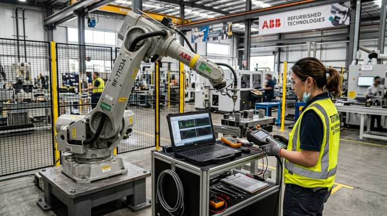
A refurbished FANUC robot can potentially provide the movement platform for large-format extrusion when its mechanical condition, controller, reach, payload, and communication capabilities match the application.
The assessment should verify:
- robot model and usable working envelope;
- controller generation;
- program-memory limits;
- offline-programming compatibility;
- available industrial communication;
- external-axis support;
- mechanical condition and backlash;
- brakes, motors, encoders, and cabling;
- system backups and installed options;
- spare-parts and service availability.
The extrusion equipment must also be engineered and commissioned for the exact robot and controller.
A lower robot purchase price does not eliminate the cost of:
- the WELDPLAST or alternative extrusion module;
- material-delivery equipment;
- mounting and hoses;
- software and postprocessing;
- simulation;
- safety equipment;
- installation;
- calibration;
- material testing;
- commissioning and support.
RHTS provides new and refurbished industrial robots that can be evaluated as platforms for robotic extrusion and additive-manufacturing research.
What Are the Main Limitations of This Type of System?
- The robot arm is not the complete printer. Extrusion, material feed, control, software, and safety must be integrated.
- Material behaviour limits geometry. Shrinkage, cooling, warping, and layer adhesion affect the output.
- Robot reach is not equal to print volume. Tool orientation, hoses, collisions, and joint limits reduce the usable envelope.
- Modularity creates assembly challenges. Connections and tolerances must be designed and tested.
- Repeatability does not guarantee component accuracy. Calibration and thermoplastic deformation remain critical.
- Surface quality may require finishing. Large extrusion beads remain visible unless machined, sanded, or coated.
- Structural claims require validation. Printed architectural geometry is not automatically construction-approved.
- Long paths create large programs. Path density and controller capacity must be managed.
- The process requires specialist knowledge. Robotics, extrusion, materials, design, and assembly must be coordinated.
- Economics remain application-specific. A technically possible component may not be commercially viable.
How to Evaluate a FANUC and Leister Robotic Printing Project
Robotic Extrusion Evaluation Framework
- Application: What architectural or physical object must be produced?
- Component Strategy: Will the result be printed as one object or as assembled modules?
- Material: Which thermoplastic will be used, and how does it cool and deform?
- Extruder: What output, temperature, nozzle, and material-feed system are required?
- Robot: What reach, payload, controller, and mounting configuration are necessary?
- Path: How will layers, nozzle orientation, start-stop behaviour, and corners be controlled?
- Software: How will geometry be sliced, simulated, postprocessed, and transferred?
- Calibration: How will the digital model align with the nozzle and platform?
- Assembly: How will modules connect, align, and transfer loads?
- Quality: What dimensional, surface, and mechanical requirements apply?
- Safety: Which thermal, electrical, pressure, and robot-motion hazards must be controlled?
- Support: Who will integrate, test, operate, and maintain the complete system?
If the component, material, assembly, and quality requirements are not defined, selecting the FANUC model or extrusion equipment is premature.
Frequently Asked Questions
What Was the FANUC and Leister 3D-Printing Project?
It was a Politecnico di Milano research project that integrated a Leister WELDPLAST 600-i extrusion module with an anthropomorphic FANUC robot to produce large plastic elements for modular architectural configurations.
What Is the WELDPLAST 600-i?
The WELDPLAST 600-i is a modular Leister extrusion unit designed for automated plastic extrusion welding and large-format 3D-printing processes.
Is the WELDPLAST 600-i a Complete 3D Printer?
No. It must be integrated with a robot or machine, material supply, control system, digital path-planning workflow, build platform, and safety equipment.
Why Use a FANUC Robot for Large-Scale Printing?
An industrial FANUC arm can provide six-axis movement, industrial payload capacity, programmable paths, and a large working envelope suitable for carrying an extrusion module.
What Is Discrete Architecture?
Discrete architecture creates larger configurations from separately manufactured components. In robotic printing, modules can be produced individually and assembled according to a shared geometric and connection system.
Can the System Print an Entire Building?
The documented project focused on large modular elements. Printing an entire building would require additional solutions for scale, mobility, structure, regulations, installation, and environmental exposure.
Can the Printed Elements Carry Structural Loads?
Potential structural use would require material testing, connection engineering, manufacturing quality control, long-term performance analysis, and compliance with applicable regulations.
Can a Refurbished FANUC Robot Be Used With a Leister Extruder?
Potentially, when the robot’s condition, payload, reach, controller, communication interfaces, and software compatibility support the complete extrusion system.
Does the System Automatically Reduce Material Waste?
Additive manufacturing can place material according to the generated geometry, but actual waste depends on failed prints, testing, supports, trimming, assembly, material preparation, and end-of-life handling.
The Project Demonstrates Integration, Not Automatic Architectural Transformation
The FANUC and Leister project at Politecnico di Milano is important because it demonstrates how an industrial robot and modular extrusion system can be integrated for large-scale architectural experimentation.
The robot provides controlled multi-axis movement. The WELDPLAST 600-i provides thermoplastic extrusion. The digital workflow defines geometry and deposition paths. Modular design allows larger architectural configurations to emerge from individually printed elements.
None of these layers can succeed independently. The robot cannot compensate for unstable material. The extruder cannot correct an unreachable path. A printable module does not automatically create a structurally valid architectural system.
The real innovation lies in connecting design, robotics, material processing, and assembly into one research workflow.
This makes the project a useful reference for architecture studios, universities, manufacturers, and fabrication laboratories investigating large-format thermoplastic deposition. It should also be read with technical discipline: as evidence of what an integrated experimental system can achieve, rather than proof that robotic 3D printing has already replaced established construction methods.
Explore further guidance in the 3D Printing Robots section or read about Robotic 3D Printing for Art and Architecture.
Architecture studios, universities, and fabrication teams can also contact RHTS with the intended material, component dimensions, required build envelope, extrusion process, and software architecture for an initial robotic-platform assessment.