English
 Italiano
 Українська
 Русский
 Español
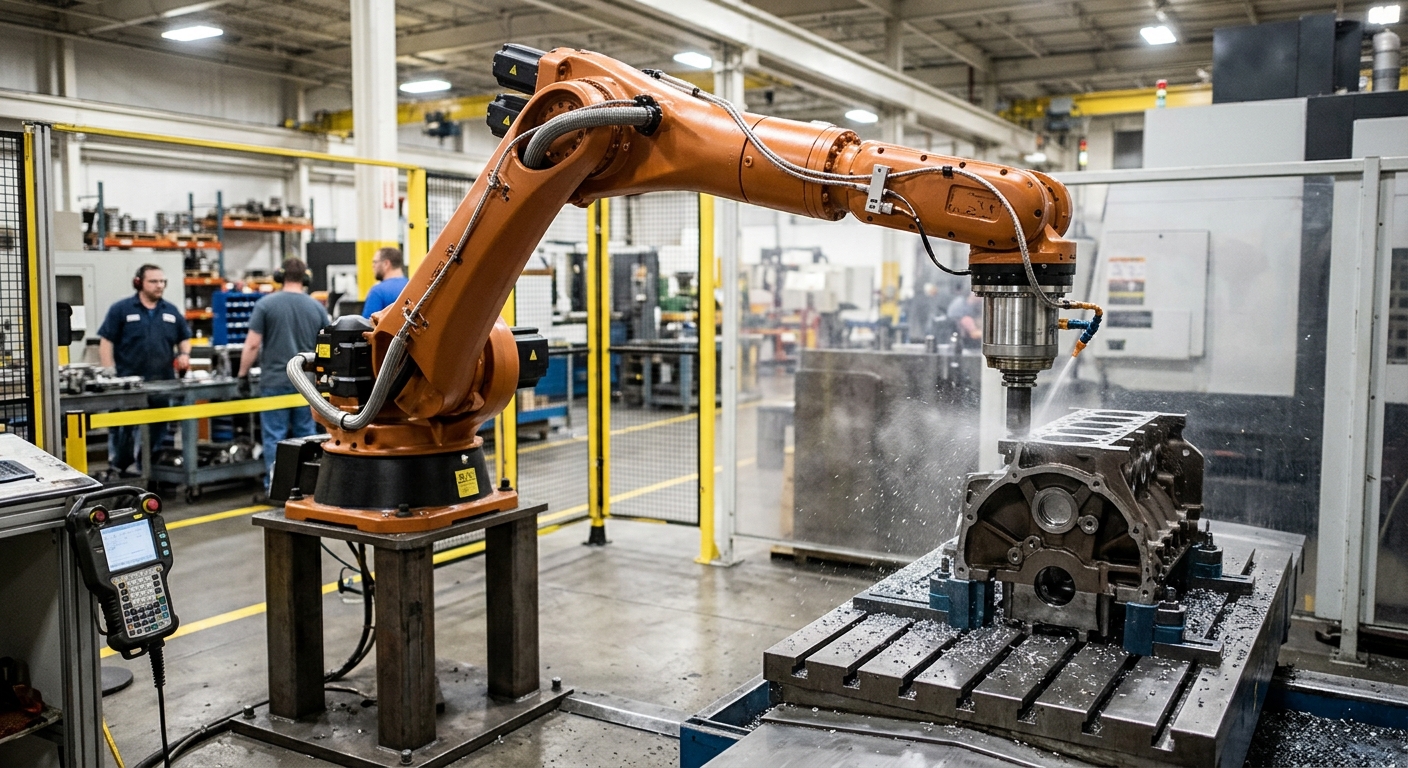

Yes, feed rate can be adjusted according to robot stiffness across the work envelope. However, the adjustment requires more than reducing machining speed whenever the robot extends its arm. Robot stiffness changes with joint configuration, tool orientation, and cutting-force direction. These variations influence how the robotic milling system responds to machining loads.
In conventional CNC machining, a relatively rigid machine structure supports the cutting process. Industrial robots have articulated joints and mechanical transmissions that introduce greater compliance. Consequently, identical cutting parameters may produce different machining results at different robot positions. A feed rate that works in a compact posture may produce excessive deflection or vibration elsewhere.
Engineers can address these differences through stiffness analysis, machining simulations, controlled cutting trials, and position-dependent feed rate adjustments. The objective is to maintain acceptable cutting conditions without introducing unnecessary slowdowns. This article explains how to evaluate robot stiffness, identify problematic machining zones, establish suitable feed rates, and validate their performance before production.
Why robot stiffness changes across the work envelope
An articulated industrial robot does not maintain identical mechanical stiffness throughout its reachable workspace. Its resistance to external cutting forces depends on the configuration of its joints and the direction in which those forces act.
Joint configuration and mechanical compliance
Each robot joint contributes to the overall compliance of the mechanical structure. Gear transmissions, bearings, structural members, and joint geometry influence the displacement caused by external loading.
Extended positions can increase the mechanical leverage of cutting forces. However, extension alone does not determine stiffness. Two different configurations at similar reaches may produce different tool deflections because their joint arrangements differ.
Directional stiffness at the tool center point
Robot stiffness is also direction-dependent. A configuration that resists loading effectively in one direction may respond differently to forces acting along another axis.
This distinction matters during milling because the cutting-force direction changes with tool engagement, cutter rotation, and machining orientation. Therefore, stiffness evaluation should consider the tool center point and the expected cutting-force directions.
How robot stiffness affects machining feed rate
Feed rate influences the amount of material removed by the cutting edges over time. With spindle speed and other cutting conditions unchanged, increasing feed generally increases chip load and can increase cutting forces.
Cutting forces and tool deflection
When cutting forces act on a compliant robotic structure, they can displace the tool from its intended position. This displacement may produce dimensional errors or variations in the machined surface.
Reducing feed rate can lower cutting loads in suitable conditions. Nevertheless, its effectiveness depends on tool geometry, material properties, spindle speed, cutting engagement, and the dynamic response of the complete machining system.
Why slower machining is not always better
Excessively low feed rates can create unfavorable cutting conditions. When chip thickness becomes insufficient, rubbing or ploughing may replace effective material removal, depending on the cutter and workpiece material.
Furthermore, changing feed rate does not automatically eliminate chatter. The relationship between structural vibration and machining parameters requires separate evaluation. The article on robotic milling vibration control explains how mechanical stiffness and cutting conditions interact.
How to identify low-stiffness machining zones
Before implementing variable feed rates, engineers need to understand where the robot becomes more compliant. This requires evaluating actual machining configurations rather than relying exclusively on the manufacturer’s reach specifications.
Robot simulation and stiffness mapping
Robot-specific simulation can identify joint configurations, tool orientations, and areas requiring further investigation. When a validated mechanical stiffness model is available, engineers can estimate how external loads affect tool displacement.
Stiffness maps may describe the robot’s response across selected workspace positions and loading directions. Their accuracy depends on the underlying model, calibration, payload assumptions, and mechanical condition.
Experimental measurements and cutting trials
Engineers can also evaluate selected configurations through controlled loading measurements and representative machining tests. External metrology or suitable displacement sensors can help identify position-dependent movement.
Machining trials should compare surface finish, dimensional deviation, vibration, and cutting behavior. The article on validating the robotic milling working envelope provides additional context for assessing reachable and stable machining positions.
How to calculate position-dependent feed adjustments
A practical feed rate strategy combines predicted cutting forces with the robot’s mechanical response. The purpose is to select cutting conditions that satisfy the required accuracy and stability at each machining location.
Combining stiffness and cutting-force models
Engineers can estimate force-induced displacement by combining cutting-force predictions with a suitable compliance model. For small static deflections, the basic relationship can be expressed as displacement equals compliance multiplied by force.
For robotic milling, the relationship is generally directional and involves multiple axes. A full compliance matrix provides a more appropriate representation than a single stiffness value. Dynamic vibration requires additional modeling.
Defining allowable cutting conditions
The calculated displacement must be compared with the machining tolerance and the portion of the error budget allocated to force-induced deflection. Other error sources must remain accounted for.
Engineers can then evaluate candidate feed rates at selected machining positions. The resulting feed limits should reflect cutting-force predictions, tool requirements, spindle capability, robot motion constraints, and measured process stability.
How to implement variable feed rates in robot programs
Position-dependent feed control can be introduced during CAM programming, post-processing, or through suitable controller functionality. The available method depends on the software and robot system.
One approach divides the machining path into zones with different validated feed settings. Another uses a calculated feed schedule that changes according to the robot configuration and predicted cutting loads.
Transitions between feed settings should remain smooth. Abrupt speed changes can affect acceleration, motion continuity, and cutting engagement. The resulting path must be checked against controller limitations and machining requirements.
What other factors must be considered?
Robot stiffness alone cannot determine a suitable feed rate. Tool projection, spindle mounting, workpiece support, and material characteristics also influence cutting behavior.
For example, a compliant workpiece may deform even when the robot maintains a favorable posture. Similarly, excessive tool overhang can create deflection that feed rate adjustments cannot fully correct.
Machining strategy also matters. Reducing radial engagement or changing the cutting direction may provide a better solution than lowering feed rate alone. The guide to robotic milling cutting parameters examines these interacting process variables.
Practical checklist for stiffness-based feed rate planning
Before changing production programs, engineers should evaluate the mechanical configuration and machining conditions systematically. The following checks help establish a traceable process.
- Record robot configurations: Identify joint positions, tool orientations, and arm extension throughout the machining path.
- Evaluate directional stiffness: Examine compliance in the directions of expected cutting forces, particularly near extended configurations.
- Review cutting engagement: Record cutter diameter, axial depth, radial engagement, spindle speed, and programmed feed rate.
- Estimate machining forces: Use an appropriate cutting-force model or representative cutting measurements for the selected material and tooling.
- Identify critical path regions: Locate configurations where predicted displacement, vibration, or motion constraints may affect machining quality.
- Establish candidate feed settings: Select feed rates that maintain suitable chip formation while respecting estimated force and deflection limits.
- Validate representative zones: Compare dimensional results, surface finish, and vibration under controlled machining conditions.
- Document approved parameters: Record the tested robot configurations, feed settings, tool assemblies, and inspection results for production reference.
How to validate feed rate adjustments before production
Validation should use representative workpieces, cutting tools, fixtures, and robot configurations. A successful trial in one workspace location does not establish performance throughout the complete machining envelope.
Engineers should compare machining results before and after introducing the feed schedule. Any improvements must be evaluated against dimensional requirements, surface quality, cycle time, and process repeatability.
Safety validation remains separate from machining optimization. The applicable integration requirements are addressed in ISO 10218-2:2025 for industrial robot applications and robot cells. Changes to machining programs must remain consistent with the cell’s risk assessment and operating limits.
For applications involving large components, varying robot configurations, or demanding surface requirements, contact Robotic Hi-Tech Solutions to discuss machining conditions, robotic cell configuration, and the technical information required for process evaluation.
FAQ’s
Can feed rate change automatically according to robot stiffness?
Yes, if the programming environment or controller supports the required strategy. Implementation may use precomputed feed schedules, external software, or compatible adaptive control functions.
Does robot stiffness always decrease when the arm extends?
No. Extension can increase compliance, but the actual response also depends on joint configuration, tool orientation, loading direction, and mechanical design.
Can reducing feed rate eliminate robotic milling vibration?
Not necessarily. Lower feed can reduce cutting forces under suitable conditions, but vibration also depends on spindle speed, structural dynamics, tooling, and workpiece support.
Is a stiffness model necessary for variable feed control?
A stiffness model supports systematic prediction. However, engineers can also develop experimentally validated feed schedules for specific machining zones without modeling the complete workspace.
Can CAM software calculate stiffness-based feed rates?
Some specialized workflows can combine robot configuration data, mechanical models, and machining parameters. Standard CAM software does not necessarily include this capability.
Should feed rate change during finishing operations?
It may be beneficial where robot compliance affects surface quality or dimensional accuracy. Adjustments should preserve suitable cutting conditions and smooth motion.
Can stiffness-based feed control improve machining accuracy?
It can reduce force-induced errors when cutting loads and mechanical compliance are correctly evaluated. It cannot independently correct calibration errors, unstable fixtures, or unsuitable tooling.
How should engineers verify a stiffness-based feed schedule?
They should perform representative cutting trials across critical workspace configurations, measure machining results, and compare the findings with defined production acceptance criteria.