English
 Italiano
 Українська
 Русский
 Español
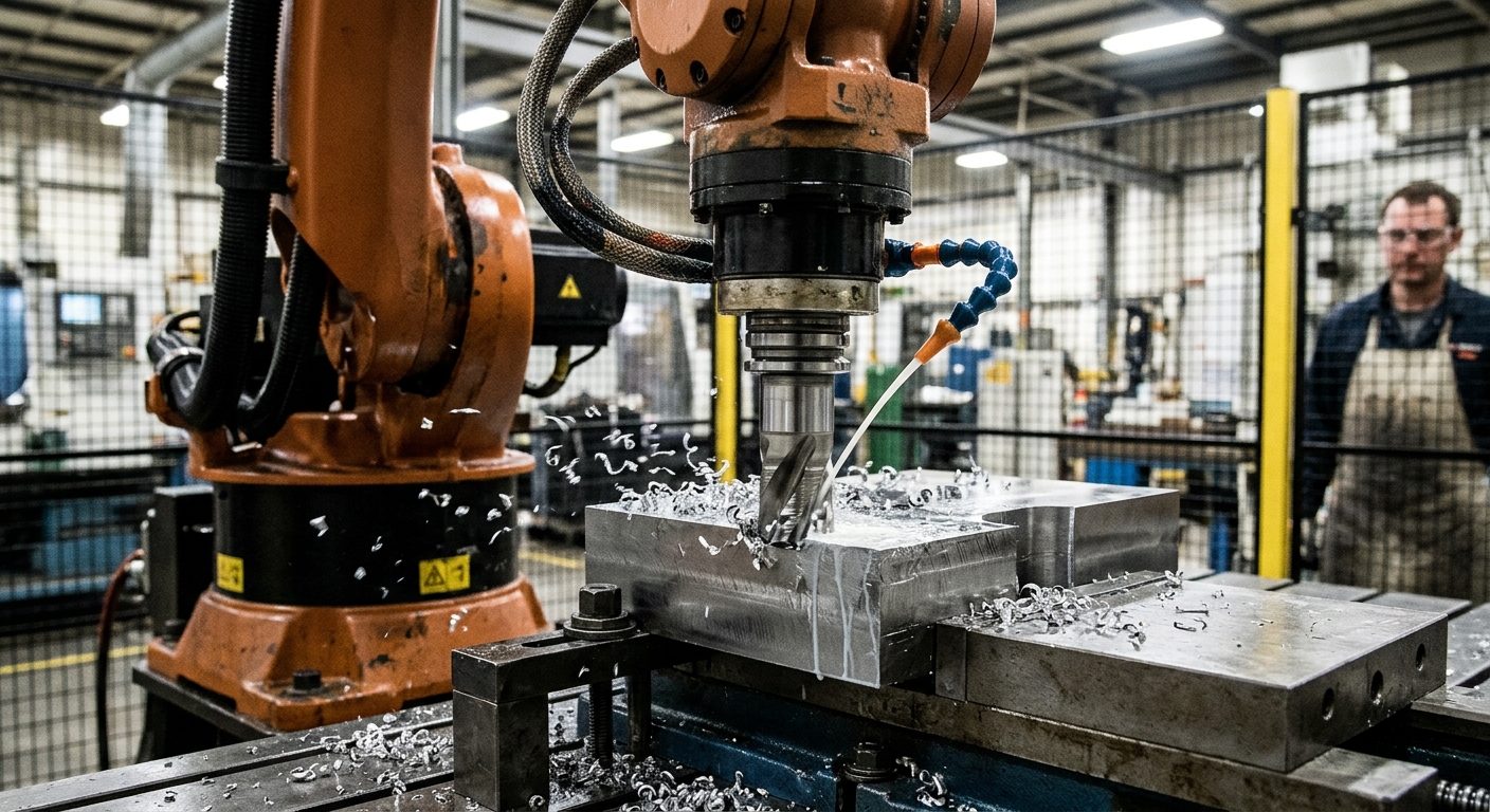

Chip recutting damages surface quality in robotic milling when loose machining chips remain near the cutting tool and enter the cutting zone again. Instead of removing only the intended workpiece material, the rotating cutter strikes or traps previously removed chips. This secondary contact can scratch the surface, increase friction, disturb cutting forces, and accelerate tool wear. The result may be visible machining marks even when the programmed toolpath appears correct.
The problem becomes more difficult to control in robotic milling because the spindle changes position and orientation throughout the operation. Large workpieces, curved surfaces, deep pockets, and different robot configurations influence where chips accumulate. A chip-removal method that works in one position may become ineffective when the robot reaches another area.
Preventing chip recutting requires coordinated control of chip formation, evacuation, cutting parameters, and toolpath design. Engineers must examine how chips leave the cutting zone and whether they can return during subsequent passes. This article explains the underlying mechanisms, common surface defects, and practical checks for improving machining consistency.
What causes chip recutting in robotic milling?
Chip recutting occurs when material already separated from the workpiece encounters the cutter again. Chips can remain inside cavities, collect along machining boundaries, or become trapped between the tool and the finished surface. Their movement depends on cutting direction, tool geometry, gravity, and the surrounding airflow or coolant.
How chips return to the cutting zone
Rotating cutting tools generate chips and direct them away from the cutting edges. However, nearby walls, fixtures, and surface geometry can interrupt their movement. Loose chips may bounce back, settle in recesses, or remain attached to surfaces through residual coolant. Subsequent tool passes can carry these particles into the cutting interface.
Why robot movement changes chip behavior
In multi-axis milling, tool orientation changes the direction in which chips leave the cutter. Robot posture also affects the relative position of the spindle, workpiece, and chip-removal equipment. Consequently, engineers should evaluate evacuation throughout the programmed path rather than at a single machining position.
How does chip recutting damage surface quality?
Surface damage depends on chip size, material properties, cutting conditions, and the type of contact. A trapped chip may slide across the machined surface or experience compression between the rotating edge and workpiece. Both situations introduce unintended mechanical contact that can affect the finish.
Scratches and localized surface marks
Hard or sharp chips can leave scratches when dragged across a finished area. Softer materials may experience localized smearing or indentation instead. These defects can appear irregularly because loose particles do not necessarily follow the programmed cutting path. Their presence should prompt an inspection of chip accumulation and evacuation.
Surface roughness and inconsistent texture
Repeated chip contact can produce uneven surface texture and localized roughness variation. However, similar defects may also result from vibration, cutter runout, or unstable feed. Engineers should distinguish these mechanisms before making adjustments. The RHTS article on spindle runout and surface finish explains another possible cause of recurring machining marks.
Why robotic milling creates additional evacuation challenges
Industrial robots provide access to large or complex workpieces, but their machining cells often differ from enclosed CNC machining centers. Chips may travel across larger spaces, accumulate around fixtures, or collect in locations that fixed extraction equipment cannot reach effectively.
Changing tool orientation and workpiece geometry
Concave features, vertical walls, and inclined surfaces create different chip accumulation patterns. A surface that sheds chips during one operation may retain them after the tool orientation changes. CAM programming should account for these conditions when selecting cutting directions and machining sequences.
Robot stiffness and cutting disturbances
Articulated robots generally have lower structural stiffness than dedicated machining centers. Their response to changing cutting forces therefore requires attention. Intermittent contact with recirculating chips can introduce additional force disturbances, although the resulting displacement depends on the complete system.
Engineers must consider robot posture, spindle mounting, tool overhang, and workpiece support together. Chip evacuation cannot correct structural instability, but removing unintended cutting contacts can reduce one source of process variation.
How cutting parameters influence chip recutting
Spindle speed, feed per tooth, cutting depth, and radial engagement determine how material separates from the workpiece. These variables influence chip dimensions, cutting forces, and evacuation behavior. Unsuitable combinations can produce chips that collect inside the machining area instead of leaving it efficiently.
Feed per tooth and chip formation
Feed per tooth describes the programmed advancement assigned to each cutting edge during rotation. An excessively low effective chip thickness can encourage rubbing rather than efficient cutting. Excessive chip loading can increase forces and generate particles that challenge the evacuation system.
Cutting parameters should follow the tool manufacturer’s recommendations and be validated for the actual material and robot configuration. Adjusting feed alone will not solve chip recutting when the underlying problem is poor chip removal.
Which evacuation methods reduce chip recutting?
Effective chip evacuation removes particles before another cutting edge or tool pass contacts them. The appropriate method depends on workpiece material, cutting conditions, enclosure design, and environmental controls. Airflow, lubrication, and coolant delivery must reach the actual cutting zone.
Directed air can remove chips from relatively accessible areas, but uncontrolled airflow may spread particles elsewhere. Minimum quantity lubrication combines limited lubricant delivery with an air stream. Flood coolant can transport chips and remove heat when the cell provides adequate containment and collection.
For a comparison of these methods, consult the RHTS guide to robotic milling cooling for aluminum. The appropriate selection depends on the machining process rather than a general preference for one cooling system.
How toolpaths and finishing passes affect surface damage
Toolpath design determines where the cutter engages material and where loose chips may remain between passes. A finishing operation can encounter particles left by earlier roughing cuts. This risk increases when recesses and overlapping toolpaths prevent chips from leaving the workpiece.
Separating roughing and finishing can provide an opportunity to remove accumulated material before the final pass. Engineers should also examine entry positions, travel direction, tool orientation, and whether the cutting sequence carries chips across previously finished surfaces.
Machining sequence changes must also consider robot accessibility and fixture stability. The RHTS article on tool balancing in high-speed robotic milling provides complementary information about another factor affecting machining stability.
How to diagnose chip recutting during production
Diagnosis should begin by observing the cutting process through suitable protected viewing equipment. Record where chips accumulate, when surface defects appear, and whether the problem follows a particular machining orientation. Compare these observations with the programmed operation and tool condition.
Inspect the resulting surface after the equipment reaches a safe state. Irregular scratches associated with accumulated particles may suggest recutting. Consistent periodic marks can indicate other causes. Repeat controlled test cuts after changing one variable at a time to isolate the contributing mechanism.
Chip inspection also provides useful evidence. Examine particle shape, adhesion, discoloration where applicable, and unusual fragmentation. These observations can help identify cutting or evacuation problems, although they do not independently establish their cause.
Practical checklist for preventing chip recutting
Before approving a robotic milling operation, engineers should validate chip control under representative production conditions. The following checks cover tool behavior, workpiece geometry, evacuation equipment, and the evidence needed to evaluate surface quality.
- Inspect chip accumulation: Identify pockets, fixture edges, and horizontal surfaces where particles remain after machining passes.
- Verify evacuation direction: Check whether air or coolant reaches the cutting zone throughout the robot’s programmed orientations.
- Review cutting parameters: Compare spindle speed, feed per tooth, and engagement against tool and material recommendations.
- Examine cutting edges: Look for wear, adhesion, chipping, or damage that may affect chip formation.
- Evaluate toolpath sequencing: Identify finishing passes that encounter chips remaining from earlier operations.
- Assess chip collection: Confirm that extraction, filtration, and collection equipment can handle the generated material.
- Measure surface condition: Compare inspected surfaces or roughness measurements against the specified acceptance criteria.
- Document controlled trials: Record tool condition, cutting parameters, robot posture, evacuation settings, and observed defects.
Chip evacuation also requires a suitable safety assessment. The OSHA technical guidance on industrial robot system safety discusses safeguarding, risk assessment, and worker protection. Any proposed chip-removal arrangement must remain compatible with the cell’s protective measures.
Where persistent surface defects require changes to tooling, programming, or cell configuration, manufacturers can contact Robotic Hi-Tech Solutions to discuss the machining application and its technical requirements.
Frequently asked questions
What is chip recutting in robotic milling?
Chip recutting occurs when previously removed workpiece material contacts the cutting tool again. It can cause scratches, irregular surface texture, additional cutting forces, or tool wear.
Can chip recutting damage a cutting tool?
Yes. Repeated contact with loose chips may contribute to edge damage or wear. The severity depends on chip properties, tool material, and cutting conditions.
Does chip recutting always increase surface roughness?
No. Its effects depend on where particles contact the workpiece. Some defects remain localized and may not substantially change roughness measurements over a larger area.
Can compressed air prevent chip recutting?
Directed air can improve evacuation when it reaches the cutting zone. Its effectiveness depends on nozzle placement, chip characteristics, workpiece geometry, and containment arrangements.
Is chip recutting more common during finishing?
It can become particularly noticeable during finishing because unwanted particle contact affects the final surface. Chips remaining from roughing may also contribute to the problem.
Can toolpath programming reduce chip accumulation?
Yes. Tool orientation, cutting direction, and operation sequencing influence chip movement. Programming changes should be evaluated alongside the evacuation system.
How can operators distinguish recutting from vibration marks?
Irregular scratches associated with trapped chips may suggest recutting. Repeated, periodic marks may indicate vibration, although tool condition and runout must also be investigated.
Should chip evacuation be validated before production?
Yes. Representative machining trials can identify accumulation zones and ineffective nozzle positions. Surface inspection and documented cutting conditions help verify whether corrective changes work.