English
 Italiano
 Українська
 Русский
 Español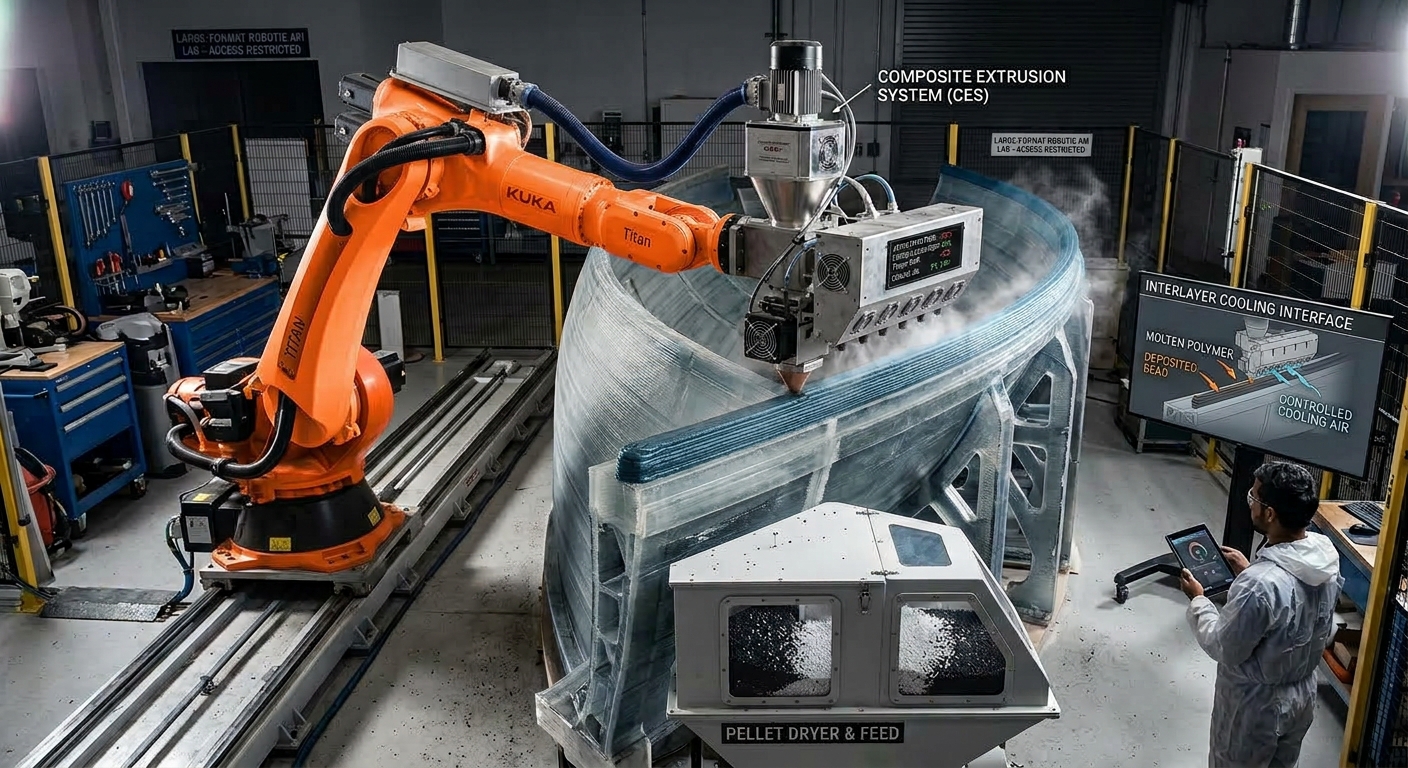

What is interlayer cooling in Large-Format Printing?
Interlayer cooling is the thermal change that occurs between depositing one polymer layer and placing the next layer over it. It affects whether the existing layer is firm enough to support additional material while remaining warm enough to form an effective bond with the new bead.
In large-format polymer 3D printing, managing this cooling period is difficult because layer times, bead dimensions, material volume, geometry, airflow, and ambient conditions can change throughout the build. Excessive cooling may weaken bonding, while insufficient cooling may allow deposited material to deform. The objective is therefore a controlled thermal condition rather than the lowest possible temperature.
This article explains how interlayer cooling influences bonding, shape retention, warping, dimensional stability, and production planning.
Why interlayer cooling affects polymer bonding
Temperature influences contact between layers.
When a new bead is deposited, its surface contacts the layer below. The temperatures of both layers influence how the polymer surfaces conform and bond. If the previous layer has cooled too far, the incoming material may not create sufficient interfacial contact under the selected process conditions.
Layer bonding also depends on material formulation, contamination, deposition pressure, bead shape, nozzle distance, and the time separating consecutive passes. Cooling is therefore one part of the bonding process, not an independent guarantee of mechanical performance.
Large parts create uneven thermal histories.
A short perimeter may receive its next layer while it is still relatively warm. A long perimeter may cool much further before the nozzle returns. The same programmed extrusion settings can consequently produce different thermal conditions in separate regions of one component.
This effect becomes more complex when a layer contains thin walls, wide sections, corners, pauses, or isolated features. Path planning must consider elapsed time between passes, not merely the nominal layer number. A general overview of applications and design considerations is available in this article on large-format 3D printing for design and architecture.
What happens when cooling is insufficient or excessive?
Too little cooling reduces shape retention.
If a deposited layer remains too soft, the weight and pressure of subsequent material can compress it. Beads may spread laterally, corners may lose definition, walls may lean, and unsupported features may sag. The nozzle can also disturb material that has not developed enough stiffness to support the next pass.
Adding more cooling is not automatically the correct response. The cause may instead be excessive material temperature, an unsuitable deposition rate, poor bead dimensions, inadequate layer time, or geometry that lacks sufficient support during printing.
Too much cooling can reduce interlayer adhesion.
Strong airflow, long pauses, or a cold production environment can lower the surface temperature before the following layer arrives. The new bead may appear correctly positioned while forming a weaker interface than intended. Separation may become visible during printing, finishing, handling, or mechanical testing.
Fast and uneven cooling can also contribute to differential shrinkage. Regions that cool at different rates may contract differently, encouraging distortion, lifted edges, or residual stress. The severity depends on the polymer, reinforcement, geometry, restraint, and temperature distribution throughout the part.
How part size and geometry change cooling behavior
Layer time varies as the geometry changes
Large-format components rarely maintain a constant cross-section from bottom to top. As the perimeter becomes longer or shorter, the time before the robot returns to a given location changes. Features printed near the end of a long path may therefore experience a different cooling interval from features printed near its beginning.
Thick intersections and dense sections tend to retain heat differently from thin walls and exposed edges. Corners can also cool differently because their surface exposure and robot deceleration patterns differ from those of straight segments. These variations should be evaluated by region rather than reduced to one average layer temperature.
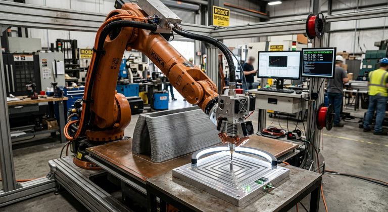
Tool positioning must remain reliable during these assessments. Incorrect nozzle position or orientation can create defects that resemble thermal problems, so extruder TCP calibration in robotic 3D printing should be verified before cooling parameters are changed.
How can Interlayer cooling be controlled?
Control methods include adjusting robot speed, extrusion temperature, programmed dwell time, layer sequence, local airflow, enclosure conditions, and the number of parts printed in one cycle. Each change affects more than cooling. Reducing speed, for example, also changes the relationship between material flow and bead geometry unless extrusion is adjusted accordingly.
Fans can accelerate cooling, but their position and direction matter. Airflow concentrated on one face may create a thermal imbalance across the component. Enclosures can reduce uncontrolled drafts and ambient fluctuations, although they require appropriate temperature monitoring and safe handling of heat and process emissions.
Path planning offers another control method. The robot can alternate between distant regions, reorder features, or introduce a validated pause before returning to a heat-sensitive area. A real application using industrial robots and polymer extrusion is described in this Nagami and ABB robotic 3D printing example.
Eight checks for evaluating the cooling strategy
An interlayer cooling study should connect measured process conditions with visible defects and verified part performance. The following checks provide a practical starting point:
- Record the material configuration: document the polymer grade, reinforcement, drying condition, batch information, and handling procedure used for the test.
- Measure actual layer time: identify the elapsed time before the nozzle returns to representative walls, corners, intersections, and isolated features.
- Track relevant temperatures: monitor the material, nozzle, deposited surface, build environment, and any controlled enclosure according to the equipment available.
- Inspect airflow: locate fans, extraction points, open doors, ventilation outlets, and other sources that can cool one region faster than another.
- Compare bead geometry: check whether spreading, compression, sagging, gaps, or inconsistent height correspond with hotter or colder areas.
- Examine layer interfaces: inspect representative sections for separation or irregular contact, especially after pauses and major path transitions.
- Evaluate dimensional change: compare the printed geometry after deposition and after the part reaches a stable temperature.
- Validate representative samples: use test features or parts that reproduce the intended material, geometry, layer time, orientation, and environmental conditions.
Change one controlled variable at a time where practical. Simultaneous changes to airflow, temperature, speed, and path sequence may improve a print, but they make it difficult to determine which adjustment produced the result.
How should cooling be monitored and validated?
Surface-temperature measurements can help identify trends, but the selected instrument and method must be suitable for the material and surface. Infrared readings may be affected by emissivity, viewing angle, distance, reflections, and surface condition. Measurement locations and procedures should therefore remain consistent during comparisons.
Visual inspection alone cannot confirm interlayer strength or validate interlayer cooling. A component can look acceptable while containing weak interfaces, and a visible surface line does not necessarily establish the cause of a defect. Validation should reflect the component’s actual requirements and may include dimensional inspection, sectioning, or appropriate mechanical evaluation.
Process documentation should record the settings and conditions that influence thermal behavior. Companies developing their procedures can consult the ISO standards catalogue for applicable additive-manufacturing, machinery, testing, and quality-management documents. The relevant standards depend on the application, material, equipment, and intended use.
FAQ
Does every layer need to reach the same temperature?
Not necessarily. The acceptable temperature range depends on the material, geometry, deposition strategy, and performance requirements. Consistent results matter more than imposing one universal temperature on every process.
Can a fan solve overheating during printing?
A fan may help a layer develop sufficient stiffness, but uncontrolled airflow can cause uneven cooling or reduce bonding. Its position, flow, timing, and effect on the complete part should be validated.
Does a longer layer time always improve print quality?
No. A longer interval may improve shape retention but allow the previous layer to cool excessively. The appropriate interval balances structural support with adequate bonding conditions.
Can extrusion temperature compensate for a cold previous layer?
Higher extrusion temperature may change interfacial conditions, but it also affects viscosity, bead shape, residence time, and material stability. It should not be used as an automatic correction without testing.
Why do corners sometimes behave differently from straight walls?
Robot speed, material accumulation, surface exposure, and airflow can change near corners. These factors may alter both bead geometry and local cooling relative to a continuous straight segment.
Can interlayer cooling cause warping?
Cooling can contribute to warping when thermal contraction varies across the component. Material behavior, geometry, build-surface restraint, reinforcement, and temperature gradients also influence distortion.
Should cooling parameters remain fixed throughout the build?
Not always. Changing cross-sections and layer times can require different settings during separate build stages. Any programmed adjustment should be validated to avoid abrupt thermal or geometric transitions.
How can cooling defects be separated from extrusion defects?
Verify material flow, robot speed, nozzle distance, calibration, bead dimensions, and environmental conditions separately. Controlled tests and process records help determine whether a defect follows temperature, flow, geometry, or motion changes.
Establishing a repeatable thermal process
Effective interlayer cooling keeps deposited material stable enough to support the build without allowing the bonding surface to become unsuitable for the next bead. Because geometry and layer time change during large prints, this balance must be evaluated across representative regions and build stages.
A dependable procedure combines controlled material preparation, coordinated robot motion and extrusion, thermal monitoring, consistent environmental conditions, and part-specific validation. For assistance evaluating a polymer extrusion cell or planning process trials, manufacturers can contact Robotic Hi-Tech Solutions with information about the material, component geometry, production objective, and existing equipment.