English
 Italiano
 Українська
 Русский
 Español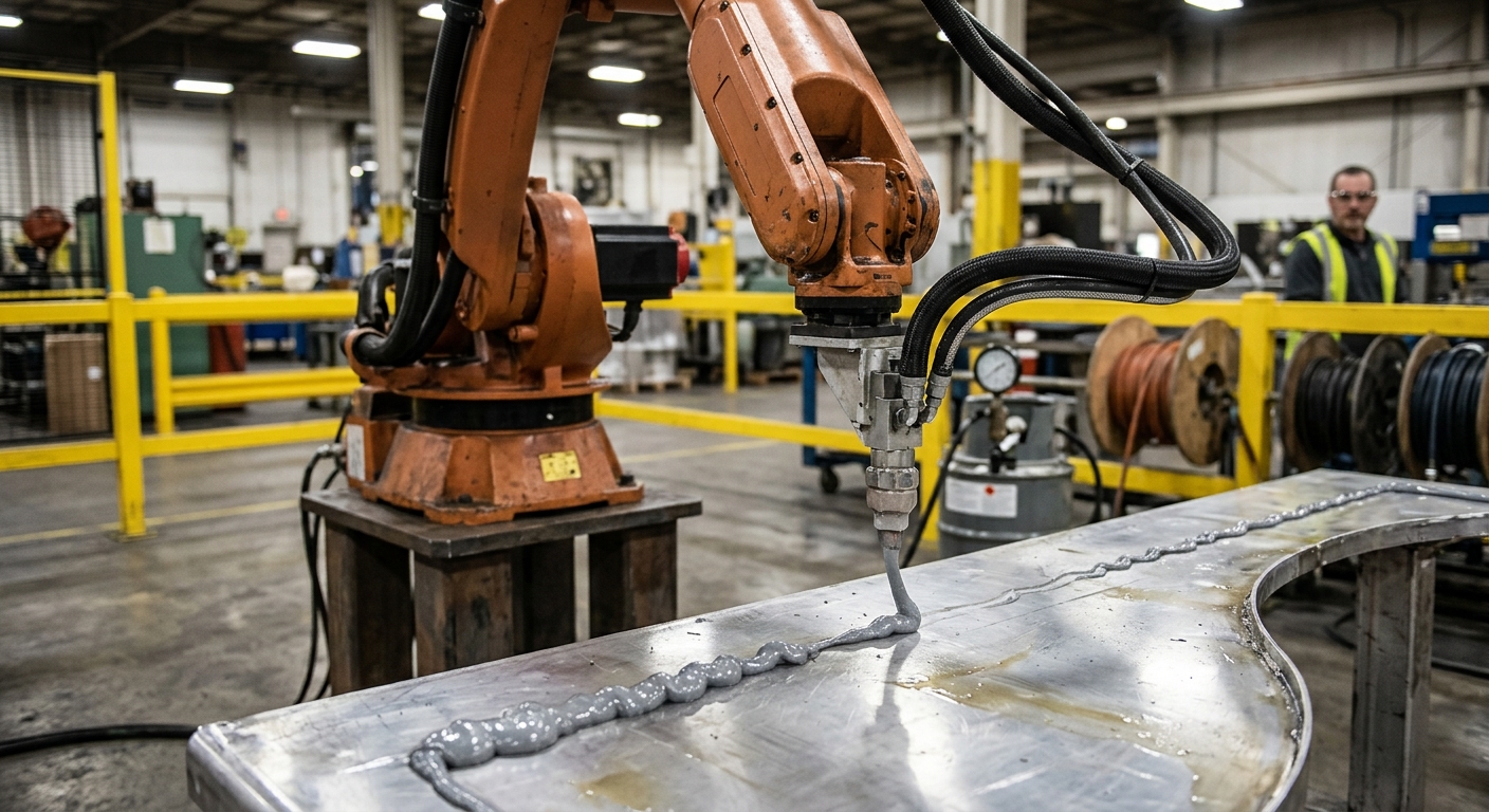

Feed pulsation creates defects in large-format robotic printing because the material does not leave the nozzle at a steady rate. When flow rises and falls while robot speed remains constant, the deposited bead alternates between excess and insufficient material. The result may include changing bead width, inconsistent layer height, surface waves, gaps, local bulging, or poor contact between adjacent paths.
The source is not always the extruder itself. Feed pulsation can begin in a pump, screw feeder, hopper, hose, material-conditioning unit, control signal, or transition between process states. Compressible material and flexible delivery lines may also store and release pressure, making the defect appear some distance after the event that caused it.
Effective troubleshooting therefore requires simultaneous examination of material delivery, extrusion pressure, motor behavior, robot velocity, and deposited geometry. This article explains how pulsating flow becomes a visible defect, how to separate it from robot-motion problems, and which measurements help identify the actual source without relying only on the appearance of the finished print.
What Is Feed Pulsation in Robotic Printing?
Feed pulsation is a repeated or irregular variation in the amount of material delivered through the nozzle over time. Instead of producing a stable output for a given command, the extrusion system alternates between higher and lower flow. The variation may be periodic, associated with each rotation or pump cycle, or intermittent because of material bridging, trapped air, changing resistance, or control instability.
Flow rate and deposited volume
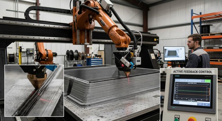
Bead geometry depends on the relationship between volumetric flow, nozzle geometry, robot travel speed, nozzle distance, and material behavior. If robot velocity and nozzle position remain unchanged while flow increases, more material is placed along the same path length. If flow falls, less material is deposited. A general overview of how the tool and robot operate together is available in this guide to 3D printing with a robotic arm.
Why Feed Pulsation Produces Visible Defects
Bead width and layer height variation
Excess flow commonly makes a bead wider or higher than intended, although the exact shape depends on confinement, nozzle clearance, material viscosity, and support from the previous layer. Reduced flow can create a narrow or low bead. Repeated flow variation produces a ribbed or wavy surface whose spacing may correspond to the frequency of the disturbance and the robot’s travel speed.
Gaps, overlaps, and weak interfaces
A low-flow interval may leave incomplete contact between neighboring beads or between successive layers. A high-flow interval can push material sideways, close planned openings, or distort an adjacent path. Interface quality cannot be judged from bead width alone because adhesion also depends on material condition, deposition timing, surface state, and the process used.
The problem becomes more pronounced at corners and path transitions. Robot speed may change while stored pressure remains in the delivery system. If extrusion output does not respond at the same rate as robot movement, material can accumulate during deceleration or become insufficient during acceleration.
Where Material Feed Pulsation Begins
Mechanical sources
Rotating feeders and positive-displacement devices may generate cyclic output when their delivery mechanism does not produce perfectly uniform displacement. Worn components, inconsistent screw filling, drive backlash, changing inlet conditions, or an unstable coupling can increase the variation. Diagnosis should compare the pulsation frequency with feeder rotation, motor speed, or pump cycles rather than assuming a component is defective from appearance alone.
Material and delivery-line sources
Material can bridge inside a hopper, enter the feed mechanism unevenly, separate into constituents, or carry trapped air. In pellet extrusion, inconsistent filling of the screw can change output. In pumped mixtures, changes in consistency or restrictions inside the hose can alter pressure and delivery. Flexible hoses and compressible materials may delay the response between a command and the resulting nozzle flow.
Nozzle restrictions are another possible source. Accumulated material, a changing outlet condition, or particles that approach the nozzle opening size can raise resistance. Pressure may build behind the restriction and then release, producing an intermittent surge rather than a steady reduction in output.
How to Distinguish Feed Pulsation From Robot Motion Errors
Compare defect timing with process signals.
A repeating surface pattern does not prove that material flow is responsible. Robot velocity fluctuation, path segmentation, mechanical vibration, nozzle-distance changes, or orientation-dependent calibration errors may create similar marks. The investigation should determine whether the defect follows time, traveled distance, feeder rotation, robot posture, or a specific program event.
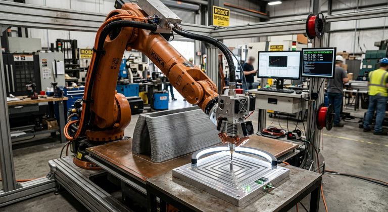
Run a controlled straight path at stable speed and orientation, where permitted by the validated process. Record extrusion commands, feeder speed, robot speed, and available pressure or motor-load signals. If bead variation continues while robot motion is stable, the material-delivery system becomes a stronger suspect. If the defect appears during orientation changes, extruder TCP calibration and nozzle positioning should also be checked.
How Feed Stability Should Be Measured
Visual inspection is useful for finding where a defect appears, but it cannot quantify the cause. A practical test may collect extruded material for a defined time under controlled conditions, measure bead geometry along a test path, or compare process signals on a common timeline. The suitable method depends on the material, equipment, scale, and required accuracy.
Average output alone can hide pulsation. A system may deliver the correct total mass over a long test while alternating between surges and shortages during shorter intervals. Measurements therefore need enough time resolution to reveal variation relevant to bead formation. Pressure, motor torque, screw speed, pump speed, robot velocity, and output measurements are most useful when their timestamps are synchronized.
Testing should be repeatable and documented. The FANUC and Leister robotic printing case study provides related context on coordinating robot movement with an extrusion system in large-format fabrication.
Eight Checks for Diagnosing Feed Pulsation
Use the following checks to separate material, mechanical, control, and robot-related causes:
- Map the defect spacing. Measure the distance between repeated thick and thin regions, then compare it with robot speed and the timing of feeder or pump cycles.
- Verify the material supply. Inspect the hopper or supply vessel for bridging, inconsistent loading, separation, trapped air, or interruptions at the inlet.
- Inspect the feed mechanism. Check screws, pumps, couplings, seals, drives, and bearings for wear, looseness, leakage, or inconsistent operation.
- Examine the delivery line. Look for sharp bends, partial restrictions, excessive hose movement, unsuitable connections, or sections that can expand under pressure.
- Check the nozzle condition. Confirm that the outlet is clean, undamaged, correctly installed, and suitable for the material being processed.
- Compare commands with feedback. Determine whether actual motor speed, pressure, or load follows the commanded value without repeated oscillation or delay.
- Separate flow from motion. Use a simple path with controlled robot speed and tool orientation to determine whether the pattern persists without complex movements.
- Record one change at a time. Keep material, temperature, nozzle, path, and speed constant while changing only the variable under investigation.
How to Reduce Pulsation Without Hiding Its Cause
Stabilize material delivery first.
Corrective action should address the identified source. Depending on the system, this may involve restoring consistent hopper feeding, removing a restriction, repairing a worn drive, improving material preparation, reducing air entry, or correcting an unstable control loop. Changing robot speed or smoothing a toolpath may alter the visible pattern without resolving unstable flow.
Process tuning should evaluate the complete response from the feeder to the nozzle. A command change may not produce an immediate flow change because pressure and material can be stored inside the extruder or hose. Start, stop, acceleration, and corner behavior therefore require validation under realistic printing conditions.
Any inspection or adjustment performed within an industrial robot cell must follow the cell’s risk-control and energy-isolation procedures. OSHA’s technical guidance on industrial robot systems describes recognized robot hazards and safeguarding considerations, although applicable requirements must be determined for the actual installation and jurisdiction.
FAQ
Can feed pulsation occur when average flow is correct?
Yes. High-flow and low-flow periods can balance over a long measurement while still producing substantial short-term bead variation.
Does a repeating bead pattern always indicate feed pulsation?
No. Repeating patterns can also come from robot motion, vibration, path segmentation, nozzle-distance variation, or rotating mechanical components.
Can increasing extrusion pressure remove pulsation?
Not necessarily. Higher pressure may worsen surging or hose expansion if a restriction, unstable feed, or compressible material is causing the variation.
Why do defects become worse near corners?
The robot may decelerate while material continues to leave the nozzle because of stored pressure or delayed flow response, causing local accumulation.
Can software compensate for unstable flow?
Control adjustments may reduce a measured disturbance, but software cannot reliably compensate for unpredictable bridging, wear, trapped air, or changing material consistency.
Should pressure remain completely constant?
Not in every system. Some equipment produces normal pressure variation. The relevant question is whether the variation changes nozzle output enough to affect the accepted print requirements.
Can nozzle temperature cause a pulsation-like defect?
Yes. Temperature variation can change the flow behavior of temperature-sensitive materials, but its relevance depends on the material and extrusion process.
What is the best first diagnostic test?
Start with a controlled straight extrusion path while recording robot velocity and available feeder, motor, or pressure signals. This helps establish whether bead variation corresponds to flow or motion.
Final Assessment Before Production
Feed pulsation should be considered a system-level problem rather than an isolated nozzle defect. The investigation must connect the visible bead pattern with material preparation, feeder operation, delivery-line behavior, extrusion control, robot movement, and process timing. A stable average output is insufficient when short-term variation changes the deposited geometry.
Before production resumes, verify the correction through repeated test paths and inspect the resulting bead dimensions and interfaces against the application’s acceptance criteria. Teams planning or troubleshooting a large-format extrusion cell can contact Robotic Hi-Tech Solutions to discuss the material-delivery system, robot coordination, tooling, and validation requirements.