English
 Italiano
 Українська
 Русский
 Español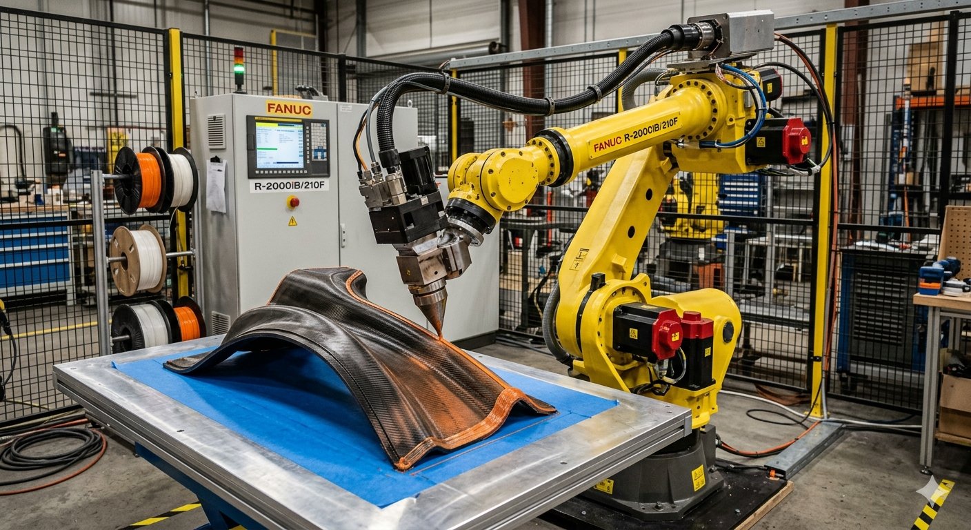

Non-planar robotic 3D printing requires more than moving an extrusion nozzle along a three-dimensional path. The robot must also control how the nozzle is oriented relative to the surface, travel direction, previously deposited material, and nearby geometry. Incorrect nozzle orientation can change nozzle clearance, affect the way material reaches the surface, and create collision risks even when the programmed path itself is geometrically correct.
Unlike conventional planar printing, where the nozzle usually maintains a fixed vertical orientation, multi-axis robotic printing can continuously rotate the tool while following curved layers or freeform surfaces. This additional freedom makes conformal and directional deposition possible, but it also means tool orientation becomes part of the process definition rather than a secondary robot setting.
This article explains how orientation affects deposition geometry, tool clearance, robot kinematics, TCP accuracy, and process validation. The objective is not to define one universal nozzle angle. Suitable orientation depends on the part geometry, extrusion process, tool dimensions, robot configuration, material behavior, and path-planning strategy.
Why Nozzle Orientation Matters in Non-Planar Printing
In a planar process, the relationship between the nozzle and build surface remains relatively predictable. In non-planar printing, the surface normal can change continuously. The robot may therefore need to rotate the extrusion tool as it travels so that the nozzle maintains an appropriate relationship with the local deposition surface.
Orientation is part of the tool pose.
A robotic tool pose contains both position and orientation. Specifying only where the nozzle tip should be located is insufficient when the tool must follow curved geometry. The rotational component determines the direction in which the nozzle points and affects the position of the rest of the extruder around that tool point.
Research on multi-axis additive manufacturing has demonstrated toolpath strategies in which nozzle orientation changes along non-planar surfaces. These strategies must account for deposition conditions as well as possible contact between the nozzle, printhead, substrate, and previously deposited material.
How Orientation Changes Deposition Geometry
Nozzle angle changes the physical relationship with the bead.
When a nozzle is tilted, its outlet no longer approaches the deposited surface in the same geometric relationship as a vertically oriented nozzle. Depending on nozzle shape and process configuration, excessive inclination can alter clearance around the outlet or cause other parts of the tool to approach the printed component.
The programmed layer distance must therefore be interpreted together with tool orientation. Bead geometry also depends on material flow, robot velocity, nozzle dimensions, temperature, and the actual gap between the nozzle and deposited material. The relationship between these variables is discussed further in the guide to controlling extrusion bead width and layer height.
Surface normal is a reference, not a universal rule.
Orienting the nozzle approximately normal to a curved surface can provide a useful starting condition for some extrusion strategies. However, following the surface normal at every point is not automatically correct. Concave regions, nearby walls, printhead dimensions, joint limits, or an unfavorable robot posture may require a different orientation.
How Nozzle Orientation Affects Material Placement
The direction in which the nozzle approaches the surface can influence where material is placed relative to the intended path. This becomes particularly significant when the deposited strand must follow a curved substrate or when successive paths are produced from substantially different orientations.
Orientation and bead contact must be evaluated together.
A valid process should maintain sufficient control of the nozzle-to-surface relationship for the selected material and extrusion method. Tilting the tool without considering clearance can locally increase or decrease the effective distance between parts of the nozzle and the printed surface.
Orientation problems may resemble extrusion problems. A changing bead can result from flow variation, travel-speed changes, thermal conditions, positioning errors, or nozzle geometry. Troubleshooting should therefore avoid assuming that an irregular bead is caused by orientation alone.
Robot Kinematics Can Limit the Available Orientations
A geometrically valid pose may not be a practical robot pose
A desired nozzle direction can be mathematically valid while placing the robot near a joint limit, an undesirable wrist configuration, or an inaccessible region of its workspace. Multi-axis path planning must consequently evaluate the complete robot configuration rather than assigning nozzle angles independently from robot kinematics.
Large orientation changes between neighboring path points can also require substantial joint movement. The trajectory should be checked for continuous motion, reasonable joint behavior, and transitions that the robot can execute without introducing unwanted interruptions into the deposition process.
Tool data are especially important when the robot changes posture. The article on extruder TCP calibration in robotic 3D printing explains why an incorrect tool center point can produce orientation-dependent positioning errors even when the programmed trajectory is correct.
Collision Avoidance Is a Major Orientation Constraint
Non-planar paths increase the possibility that the nozzle body, heating components, extruder, hoses, or robot wrist will approach the part from unusual directions. A tool orientation that gives good access at one point may become unsuitable several centimeters farther along the same curved path.
Collision checking should include the complete tool.
Checking only the theoretical nozzle tip is not sufficient. The physical geometry of the extrusion assembly should be represented when evaluating toolpaths because the nozzle body or other components may contact the workpiece before the programmed TCP reaches an obstacle.
Previously deposited material also matters. As the component grows, areas that were initially accessible can become obstructed. Path order and orientation therefore need to be evaluated together, especially in concave features, intersecting geometries, steep walls, and areas where the tool must move between deposited structures.
Calibration Becomes More Critical During Tool Rotation
An inaccurate TCP can remain difficult to notice when the extruder stays at one orientation. When the tool rotates, however, an incorrect TCP position may cause the physical nozzle tip to move around the intended reference instead of rotating about it. This can create changes in nozzle-to-surface distance or lateral deposition position.
For this reason, calibration should be verified across representative tool orientations, not only in one convenient vertical posture. The build frame, nozzle installation, tool-axis definition, robot condition, and any external axes should also be checked separately so one calibration error is not incorrectly compensated through another coordinate system.
Thermal process changes can further complicate diagnosis. If material deposited on a curved path has not reached a suitable condition before the nozzle returns nearby, deformation may be mistaken for a geometric orientation problem. The article on interlayer cooling in large-format polymer 3D printing provides additional context for separating thermal effects from positioning issues.
Eight Checks Before Using Variable Nozzle Orientation
A variable-orientation strategy should be validated with the actual robot, extrusion tool, part geometry, and process conditions. The following checks help identify geometric and motion problems before a complex print is released for production.
- Verify the TCP: confirm the physical nozzle tip and tool-axis definition using more than one representative robot orientation.
- Check local clearance: evaluate the nozzle, heater, extruder body, brackets, hoses, and wrist against the substrate and printed geometry.
- Review surface relationship: confirm that the programmed orientation maintains the intended nozzle-to-surface condition along curved regions.
- Inspect joint motion: identify joint limits, abrupt wrist changes, unfavorable configurations, and sections requiring excessive reorientation.
- Validate transitions: examine how the robot moves between differently oriented deposition segments and between printing and travel moves.
- Compare path and flow: check whether robot velocity and extrusion output remain coordinated when orientation changes alter robot motion.
- Test representative geometry: print curved, inclined, concave, or orientation-sensitive features before validating a complete production component.
- Inspect deposited results: compare bead position, clearance, interfaces, and surface condition with the application’s defined acceptance criteria.
How to Validate Orientation Safely Before Production
Simulation can identify many reachability, joint-motion, and collision problems before the robot runs, provided that the digital models accurately represent the real robot, tool, workpiece, fixtures, and relevant cell equipment. Simulation should then be complemented by controlled physical validation because actual tool installation and process behavior may differ from the digital model.
Initial trials should use conditions appropriate to the installed system and established cell procedures. Personnel should not enter hazardous robot areas simply to observe nozzle clearance during an automatic trajectory. OSHA guidance on industrial robot systems provides general information on robot hazards and safeguarding; applicable requirements still depend on the installation and jurisdiction.
No single orientation strategy is correct for every non-planar print. The selected approach must balance deposition geometry, clearance, robot accessibility, calibration accuracy, material behavior, and the capabilities of the extrusion system. Teams developing a multi-axis printing cell can contact Robotic Hi-Tech Solutions to discuss robot configuration, extrusion tooling, path planning, and integration requirements for a specific application.
FAQ
What is nozzle orientation in robotic 3D printing?
Nozzle orientation describes the rotational direction of the extrusion tool relative to the robot, deposition path, and printing surface. Together with nozzle position, it defines the tool pose used by the robot.
Should the nozzle always be perpendicular to the printing surface?
No. A surface-normal orientation may be useful in some processes, but geometry, collisions, robot kinematics, tool shape, and process requirements can make another orientation more suitable.
Can nozzle orientation change bead width?
It can influence the physical relationship between the nozzle and the deposited surface. Actual bead width also depends on flow, speed, material behavior, nozzle geometry, temperature, and deposition gap.
Why are orientation errors more noticeable in non-planar printing?
The tool rotates more frequently and through larger angular changes. Errors in the TCP, tool axis, clearance, or trajectory can therefore produce effects that remain less visible during fixed-orientation printing.
Can nozzle orientation prevent collisions?
Changing orientation can provide additional clearance in some regions, but it can create collisions elsewhere. The complete tool geometry and robot motion should be checked along the entire trajectory.
Does robot simulation guarantee that the nozzle will not collide?
No. Simulation depends on accurate models, calibration, tool dimensions, fixtures, and real cell conditions. It is an important validation method but does not replace appropriate physical verification.
Does changing nozzle orientation require changing material flow?
Not automatically. However, orientation changes can coincide with changes in robot velocity, clearance, or deposition conditions, so flow and motion should be evaluated together during process validation.
When should nozzle orientation be checked again?
It should be reassessed when the nozzle or extruder geometry changes, the tool mounting is modified, TCP data are updated, a new non-planar path is introduced, or unexpected clearance or deposition errors appear.