English
 Italiano
 Українська
 Русский
 Español
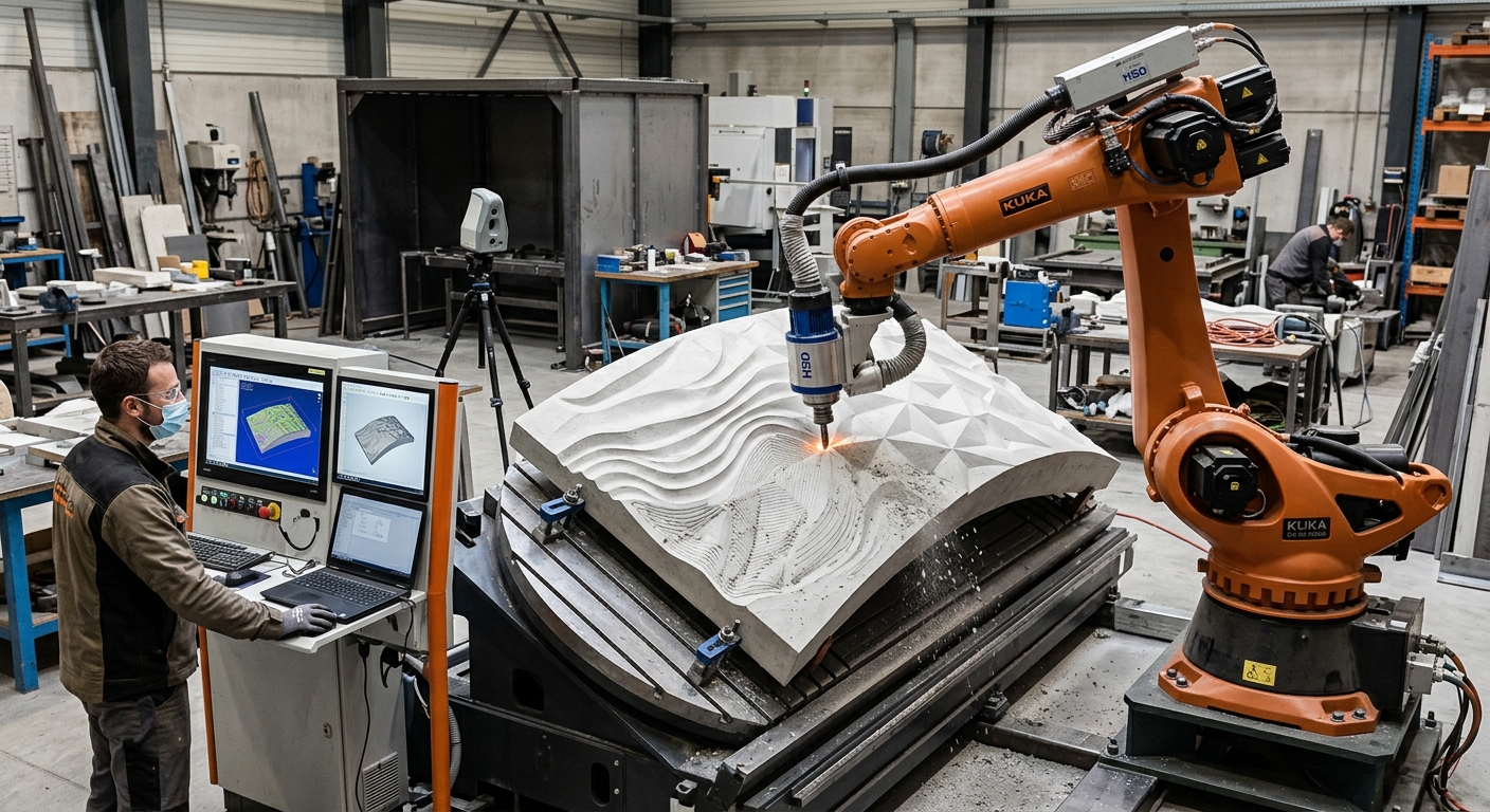

Complex architectural surfaces can be reproduced by combining 3D scanning with robotic machining. The scanner captures the geometry of an existing object, while digital modelling software prepares the information for manufacturing. A robotic system then follows programmed toolpaths to remove material from a suitable workpiece, creating a physical reproduction of the selected surface.
This workflow supports architectural ornaments, curved panels, sculptural elements, and restoration components. However, converting a physical surface into a machinable model requires several operations. Scan quality, geometric reconstruction, tool accessibility, material behaviour, and robot calibration all influence the result. Capturing detailed geometry does not automatically guarantee that the manufactured component will match the original.
This article explains how 3D scanning connects physical objects with robotic fabrication. It examines scanning methods, digital surface preparation, machining strategies, dimensional verification, and practical production limitations. The objective is to help architects, fabrication specialists, and engineers determine when this approach is technically suitable and what they must evaluate before manufacturing complex architectural components.
1. How 3D scanning supports architectural reproduction
Architectural reproduction begins with an existing physical reference or a digital design. When the original geometry is unavailable, 3D scanning can collect surface measurements and produce a digital representation. The resulting data provides a starting point for reconstruction rather than a complete manufacturing program.
Capturing complex surface geometry
Laser scanners and structured-light systems can measure visible surface geometry without direct physical contact. Their suitability depends on object dimensions, surface reflectivity, measurement requirements, and operating conditions. Recesses, narrow cavities, and hidden surfaces may require additional scanning positions or alternative measurement methods.
Understanding point clouds
A point cloud contains measured positions distributed across the scanned surface. Processing software can register multiple scans into a common coordinate system and generate a surface mesh. Registration quality matters because errors between scan positions can distort the reconstructed geometry. Reliable 3D scanning also requires adequate surface coverage.
2. Preparing 3D scanning data for robotic machining
Raw 3D scanning data often contains unnecessary points, measurement noise, or missing regions. Before machining begins, engineers must evaluate whether the model adequately describes the intended architectural surface. They should preserve relevant details while correcting defects that would interfere with machining.
Cleaning and reconstructing digital surfaces
Mesh processing can remove isolated measurements, repair selected gaps, and reduce excessive geometric density. However, automatic reconstruction may change sharp edges or ornamental details. Operators should compare modified regions with the original scan before approving the model for production.
Converting geometry into manufacturing data
Depending on the software workflow, the reconstructed geometry may remain a polygonal mesh or become a CAD surface. CAM software uses this geometry to calculate cutting paths. The RHTS article on AI-powered robotic stone carving and 3D scanning examines related decisions in sculptural reproduction.
3. How robotic machining reproduces curved surfaces
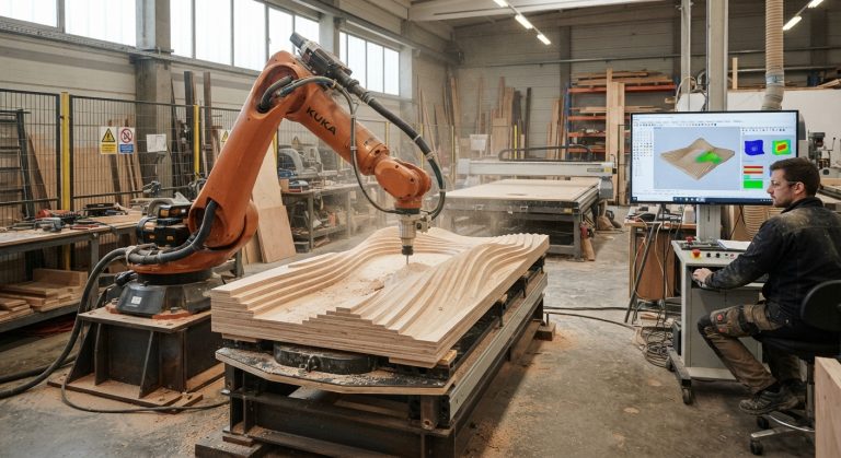
Robotic machining uses an industrial arm equipped with a suitable cutting spindle or other material-removal tool. The robot positions and orients the tool along programmed paths. Its ability to approach a workpiece from different directions can help machine surfaces that present difficult accessibility conditions.
Generating machining toolpaths
CAM software calculates tool movements using the target geometry, cutting tool, machining strategy, and material allowance. Roughing operations remove larger amounts of material, while finishing paths approach the required surface. Tool diameter and geometry determine which cavities and details the process can reproduce.
Controlling tool orientation
Tool orientation influences cutting contact, clearance, and accessibility. On curved architectural elements, the desired orientation may change continuously. The RHTS guide to parametric design and robotic fabrication explains how geometric data becomes robot targets with defined positions and orientations.
4. Selecting materials and machining strategies
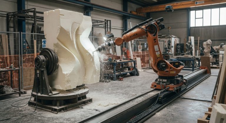
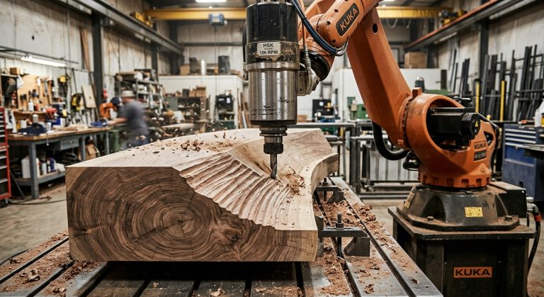
Material selection determines cutting forces, tool wear, finishing requirements, and fixture design. Architectural components may use wood, foam, stone, or other machinable materials. Each requires an appropriate cutting strategy, and the machining parameters must be established through material and equipment specifications.
Matching tools to surface details
Large tools can remove accessible material during roughing, while smaller cutters may reach narrow ornamental features. However, additional finishing passes increase machining operations. Engineers must balance surface detail, tool accessibility, and production requirements without assuming that every feature captured through 3D scanning can be manufactured.
Managing workpiece fixation
Fixtures must restrain the workpiece against machining forces while preserving tool access. Large curved parts may need multiple setups or external positioning systems. Every repositioning operation requires reliable references to maintain geometric alignment between machining stages.
5. What determines machining accuracy?
A detailed 3D scanning model does not guarantee an equally accurate manufactured surface. The complete process introduces uncertainty through measurement, model reconstruction, coordinate alignment, robot positioning, machining deflection, and inspection. Engineers should evaluate these contributors against the component’s functional and visual requirements.
Robot stiffness and cutting forces
Industrial robot arms can deflect under machining loads. The resulting displacement depends on robot configuration, structural stiffness, tool engagement, and process conditions. Selecting suitable cutting parameters and maintaining stable fixtures can reduce unwanted movement, although the achievable tolerance must be validated.
Calibration and coordinate alignment
The robot must correctly interpret the relationship between its base, the cutting tool, and the workpiece. Tool centre point calibration and workpiece coordinate definition establish these relationships. Incorrect offsets can create dimensional errors even when the digital toolpath accurately follows the intended model.
6. Validating the digital and physical results
Validation should begin before material removal. Robot simulation can identify unreachable positions, joint-limit violations, and potential collisions. These checks must include the spindle, cutting tool, fixtures, workpiece, and relevant surrounding equipment, rather than considering the robot arm alone.
Comparing the machined part with the reference
After machining, inspection can compare the finished component with the approved reference model. A registered inspection scan may reveal deviations across curved surfaces. Using 3D scanning for inspection requires appropriate measurement settings and alignment procedures. Interpretation should account for measurement uncertainty and the defined acceptance criteria.
Addressing robotic machining safety
Cutting operations introduce hazards involving moving machinery, rotating tools, expelled material, and access to restricted areas. The OSHA technical guidance on industrial robot system safety discusses risk assessment, safeguarding, and measures relevant to robotic applications.
7. Understanding architectural manufacturing limitations
Surface complexity can create problems beyond the scanner’s measurement capability. Deep undercuts may prevent cutting-tool access, while thin details can be difficult to machine without damage. Some components require sectional manufacturing, assembly, or supplementary finishing processes.
Dividing oversized architectural components
Large surfaces may exceed the available robot workspace or material stock. Dividing the design into manageable sections can address these restrictions, provided that joints, alignment references, and assembly tolerances receive appropriate attention. The RHTS article on dividing large sculptures for robotic fabrication discusses these manufacturing decisions.
Architectural restoration adds another consideration: an existing surface may contain damage, deformation, or previous repairs. Although 3D scanning records accessible geometry, it cannot determine the original appearance of missing features. Project teams must use architectural evidence and professional judgement when reconstructing damaged components.
8. Practical checklist for planning architectural reproduction
Before committing to robotic production, engineers should review the reference geometry, machining setup, and inspection requirements. The following checklist identifies eight decisions that affect whether a 3D scanning and robotic machining workflow is suitable.
- Define the reproduction objective: Determine whether the component must match existing geometry, recover missing details, or incorporate approved design changes.
- Evaluate scanning accessibility: Identify hidden surfaces, reflective materials, narrow cavities, and areas requiring additional measurement positions.
- Establish geometric tolerances: Specify acceptable dimensional deviations and identify features requiring closer inspection.
- Review digital reconstruction: Check repaired mesh regions, registration quality, surface continuity, and preserved architectural details.
- Confirm material suitability: Examine machinability, workpiece dimensions, available stock, and finishing requirements.
- Verify robot accessibility: Simulate tool orientations, joint limits, fixtures, collisions, and necessary workpiece repositioning.
- Plan machining validation: Assess cutting parameters, tool selection, calibration, and representative test features before full production.
- Define inspection procedures: Establish measurement references, acceptance criteria, and responsibilities for approving the manufactured surface.
These checks help identify limitations before machining begins. For architectural reproduction projects requiring an assessment of robotic reach, tooling, and process configuration, teams can contact Robotic Hi-Tech Solutions to discuss the proposed application and its technical requirements.
FAQ’s
Can 3D scanning reproduce an architectural surface exactly?
Scanning captures measurable surface geometry within the capabilities of the measurement system. Reproduction accuracy also depends on reconstruction, machining, calibration, and inspection. An exact match cannot be assumed.
Which architectural elements can be scanned?
Examples include decorative panels, columns, reliefs, mouldings, and sculptural components. Suitability depends on surface accessibility, dimensions, material properties, and required detail.
Does robotic machining require a CAD model?
It requires suitable digital geometry for toolpath generation. Depending on the CAM software, this may be a processed mesh or a reconstructed CAD surface.
Can robots machine stone architectural details?
Robotic systems can machine selected stone materials when equipped with appropriate tools, fixtures, and process controls. Cutting forces, tool wear, and material characteristics require evaluation.
What causes differences between scanned and machined surfaces?
Differences may result from 3D scanning uncertainty, reconstruction changes, coordinate errors, tool geometry, machining deflection, or material movement. Inspection helps identify deviations that require correction.
Can 3D scanning help restore damaged ornaments?
Yes. Scanning can document surviving geometry and support digital reconstruction. Missing details require additional references or design decisions because the scanner cannot measure absent surfaces.
Is robotic machining suitable for large architectural panels?
It can be suitable when the robot, tooling, fixtures, and workpiece positioning provide sufficient access. Oversized components may require sectional manufacturing or external axes.
How should a reproduced architectural surface be inspected?
Inspection should compare measured geometry with an approved reference using defined alignment procedures and tolerances. Visual checks may supplement dimensional measurements for decorative features.