English
 Italiano
 Українська
 Русский
 Español
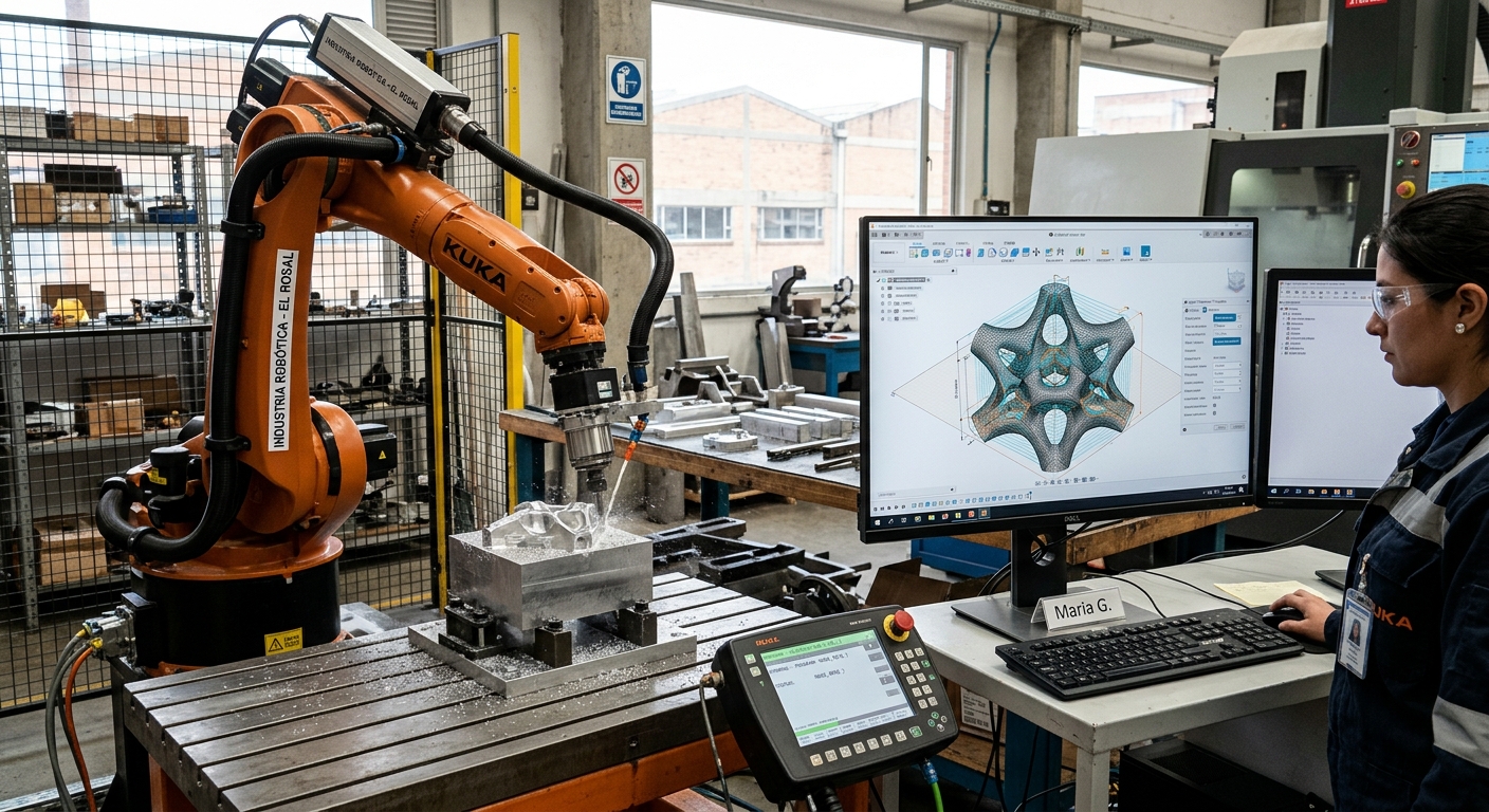

Between a parametric model and an executable robot program, several technical operations must take place. Designers generate digital geometry, but industrial robots require instructions defining movement, tool orientation, speed, and process control. The parametric robot workflow connects these requirements through manufacturing planning, toolpath generation, simulation, postprocessing, calibration, and physical testing.
This conversion matters in robotic sculpture, architectural fabrication, large-format 3D printing, and robotic milling. A surface may appear suitable for manufacturing while containing inaccessible areas or orientations that the selected robot cannot achieve. Therefore, engineers must evaluate geometric information against the robot’s mechanical limits, tooling requirements, and operating environment before production begins.
A reliable parametric robot workflow provides a structured method for translating design intentions into movements that a robot controller can execute. It also helps identify incompatibilities between software, equipment, and manufacturing processes. This article explains what happens during each conversion stage, how engineers validate robot movements, and which technical checks help prevent programming errors before physical fabrication.
1. What information does a parametric model contain?
Understanding geometry and design relationships
A parametric model defines geometry through variables, constraints, and relationships. Changing a dimension or parameter modifies connected elements according to predefined rules. However, these relationships do not automatically describe how an industrial robot should manufacture the resulting object.
The model may include curves, surfaces, reference planes, component positions, and geometric dependencies. These elements provide manufacturing information, but additional operations must convert that information into executable instructions.
Separating design geometry from fabrication instructions
Design geometry describes the intended physical result. Fabrication instructions determine how tools and materials interact during manufacturing. For example, a curved architectural panel may require several milling passes with different cutting depths and tool orientations.
This distinction is central to the parametric robot workflow. RHTS examines the relationship between geometric rules and manufacturing instructions in its article on parametric design and robotics for fabrication.
2. How does the parametric robot workflow define manufacturing operations?
Identifying the fabrication process
Before generating robot movements, programmers must establish the manufacturing operation. Milling, additive manufacturing, cutting, and assembly require different movement strategies and processing conditions. Material characteristics, tool dimensions, and surface requirements influence these decisions.
For milling, engineers consider cutting depth, tool engagement, and material removal. Additive manufacturing requires deposition paths and material-flow coordination. Assembly operations depend on gripping, component positioning, and release sequences.
Connecting manufacturing parameters with geometry
Process planning converts geometric features into manufacturing operations. A surface can determine cutting direction, while a reference curve may define the movement of an extrusion nozzle.
Within a parametric robot workflow, designers can connect manufacturing parameters to adjustable geometry. When the design changes, software may regenerate the associated paths. However, updated operations must still satisfy robot accessibility and processing requirements.
3. How does toolpath generation convert geometry into robot movements?
Creating positions and tool orientations
Toolpath generation converts geometric information into an ordered sequence of movement targets. Each target generally defines the position and orientation of the tool. The resulting trajectory describes how the tool should move relative to the workpiece.
For example, robotic milling may use surface geometry to calculate successive cutting positions. Tool orientation can follow surface normals, machining directions, or application-specific constraints.
Controlling movement continuity
Target spacing affects how closely the programmed path follows the original geometry. Excessive segmentation increases program complexity, while insufficient resolution can reduce geometric accuracy.
Engineers must also evaluate transitions between manufacturing operations. Abrupt direction changes or unsuitable stopping points can affect process consistency. For architectural components, path generation must account for the manufacturing sequence and component geometry.
Related considerations appear in RHTS’s guide to robotic sculpture fabrication and component planning, which explains how geometric decisions influence robotic access and manufacturing.
4. Why must robot kinematics be checked?
Evaluating reachability and joint configurations
Robot kinematics describes the relationship between joint positions and tool movement. A target may lie within the nominal working envelope while remaining inaccessible at the required orientation.
Simulation software evaluates possible configurations and identifies movements that exceed joint limits. It can also reveal positions near singularities, where the robot may require substantial joint movement to produce a relatively small tool displacement.
Detecting collisions and external-axis limitations
A complete simulation should represent the robot, tool, workpiece, fixtures, and surrounding equipment. Collision analysis must include approach movements, processing paths, and transitions between operations.
When the cell includes a positioner or linear track, engineers must evaluate coordinated movement between the robot and external axes. Ignoring these relationships can produce a path that appears geometrically correct but cannot execute as intended.
5. How does postprocessing create controller-compatible instructions?
Translating toolpaths into robot code
Postprocessing converts generic manufacturing paths into instructions compatible with a particular robot controller. Different robot manufacturers use different programming languages, coordinate representations, and motion commands.
Within the parametric robot workflow, the postprocessor connects digital manufacturing data with the controller’s execution requirements. Generated instructions may define target positions, movement types, reference frames, speed settings, and external equipment commands.
Coordinating movement and process equipment
Robot programs may control spindles, extrusion systems, grippers, or other manufacturing equipment through available controller interfaces. These instructions must coordinate tool movement with the intended operation.
For example, an extrusion system must activate material delivery at the appropriate stage of the path. Incorrect synchronization may create defects even when the robot follows the programmed trajectory accurately.
6. How are digital coordinates aligned with the physical robot?
Calibrating the tool center point
The tool center point, or TCP, defines the reference point used to position the robot’s tool. Incorrect calibration can introduce positional errors, particularly when the tool changes orientation.
A reliable parametric robot workflow requires tool data that corresponds to the equipment installed in the physical cell. Tool replacement, mounting changes, or recalibration may require the programmer to update reference information.
Defining workpiece reference frames
Reference frames connect digital coordinates with physical locations. The workpiece frame establishes how robot movements relate to the installed component and its fixture.
Incorrect frame definitions can shift or rotate the entire manufacturing path. Therefore, engineers must verify the relationship between digital coordinates, robot configuration, and actual workpiece placement before execution.
7. What should engineers verify before running a robot program?
Before releasing a generated program, engineers should examine the complete relationship between the design model, manufacturing path, robot configuration, and physical installation. The following eight checks help identify common technical inconsistencies.
- Model revision: Confirm that generated manufacturing paths correspond to the approved design version.
- Coordinate alignment: Compare digital model coordinates with configured robot and workpiece reference frames.
- Tool calibration: Verify TCP values, tool orientation, and relevant equipment dimensions.
- Robot reachability: Check joint limits and available configurations throughout the movement sequence.
- Collision clearance: Examine the robot, end effector, fixtures, workpiece, and surrounding equipment.
- Controller compatibility: Confirm that the postprocessor matches the robot controller and installed software configuration.
- Process synchronization: Review tool activation, material delivery, gripping, and other coordinated commands.
- Physical validation: Follow approved commissioning procedures and inspect controlled test results before production.
Simulation cannot reproduce every physical effect. Cutting forces, structural deflection, material behavior, and calibration differences may affect the final result. RHTS discusses some of these limitations in its article about robot dynamics in robotic milling.
8. How can the parametric robot workflow remain reliable during production?
Managing design revisions and program records
Changes to a digital model can affect toolpaths, manufacturing parameters, robot configurations, and equipment commands. Engineers should maintain traceable relationships between model revisions, generated programs, calibration records, and production results.
A controlled parametric robot workflow allows teams to identify which manufacturing operations require regeneration after a design modification. This reduces the risk of executing programs that no longer correspond to the approved geometry.
Integrating validation and robot safety
Technical validation must also consider the safety requirements of the complete robotic cell. Risk assessment, safeguarding, operating procedures, and commissioning activities remain necessary even when simulation reports a valid movement sequence.
The international standard ISO 10218-2:2025 for industrial robot applications and cells addresses requirements related to integration, commissioning, operation, and maintenance. Its scope does not replace additional assessments of hazards associated with specific manufacturing processes.
Organizations developing a parametric robot workflow can contact Robotic Hi-Tech Solutions to discuss robotic fabrication, equipment integration, tooling requirements, and programming considerations for their projects.
FAQ’s
Can a parametric model generate a robot program automatically?
Compatible software can automate target generation and parts of the programming process. However, engineers must still verify robot configurations, controller compatibility, manufacturing conditions, and physical execution.
What is the difference between a toolpath and a robot program?
A toolpath describes intended tool movement. A robot program contains executable instructions formatted for a particular controller, including movement definitions and potentially additional process commands.
Does every parametric robot workflow require CAM software?
No. Some applications generate robot targets directly through parametric programming tools. Machining operations commonly use computer-aided manufacturing functions to calculate suitable manufacturing paths.
Why can a geometrically correct path fail during simulation?
Geometric validity does not guarantee mechanical accessibility. A robot may encounter joint limits, collisions, singularities, or tool orientation restrictions while following the path.
Can the same robot program work with different robot brands?
Not necessarily. Controllers may use different programming languages, motion commands, and reference structures. Transferring a process between brands generally requires compatible postprocessing and validation.
What happens when the parametric design changes?
The corresponding manufacturing data may require regeneration. Engineers should verify whether the modification affects toolpaths, reference frames, processing parameters, or previously validated movements.
Can simulation guarantee accurate robotic fabrication?
No. Simulation evaluates movement using a digital representation. Physical accuracy also depends on calibration, tooling, structural behavior, workpiece positioning, and manufacturing conditions.
Why should robot program versions be recorded?
Version records connect physical components with their design and programming data. They support troubleshooting, manufacturing traceability, revision control, and consistent production procedures.