
Why Robot Dynamics in Robotic Milling Matter for Surface Quality
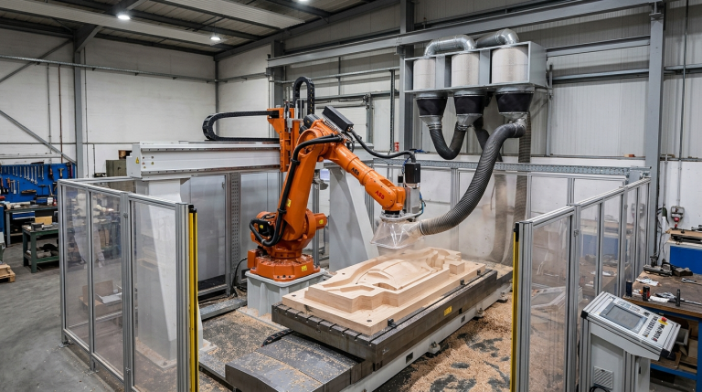
When companies evaluate robot dynamics in robotic milling, surface quality often becomes one of the most important technical questions. The issue is not only whether a robot can follow a toolpath but also whether the complete robotic milling cell can control acceleration, deceleration, stiffness, vibration, spindle behavior, and workpiece stability across a large machining envelope.
In large-format machining, surface finish is not determined only by spindle speed, cutting tool geometry, or feed rate. Robot motion dynamics also influence how consistently the tool engages with the material, especially during curves, direction changes, long passes, and transitions between different machining zones.
For manufacturers evaluating large-format machining solutions, understanding robot dynamics in robotic milling is essential for predicting both machining quality and process stability.
This is especially relevant when machining composites, aluminum, plastics, tooling board, and advanced materials, where visual quality, dimensional accuracy, edge consistency, and repeatability are part of the production requirement.
Why Robot Dynamics Matter in Robotic Milling
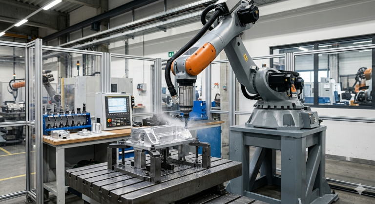
Industrial robots are articulated multi-axis systems. Unlike traditional gantry CNC machines, which are built around rigid linear axes, robots move through a changing kinematic structure. This means stiffness, inertia, and axis behavior vary with the robot’s posture and the tool’s position in the workspace.
The influence of robot dynamics in robotic milling becomes more significant as toolpaths become longer, geometries become more complex, and surface quality requirements become stricter.
In robotic milling, this matters because the cutting tool is constantly applying force to the workpiece. If the robot accelerates too aggressively, decelerates abruptly, or moves through a less rigid posture, small dynamic effects can appear in the machined surface.
These effects may include micro-vibrations, tool deflection, surface waviness, visible transition marks, edge inconsistencies, or local differences in surface roughness. In large-format machining, these problems can accumulate over long toolpaths and become more visible on finished parts.
Robot dynamics in robotic milling should therefore be treated as a design variable, not as a fixed limitation. The goal is not simply to reduce speed but to control the robot’s motion under real cutting conditions.
Acceleration, Deceleration, and Surface Finish
Acceleration and deceleration influence how smoothly the cutting tool enters, follows, and exits each section of the toolpath. High acceleration can improve cycle time, but if the mechanical system is not tuned correctly, it can also introduce vibration or instability.
During straight passes, the robot may maintain stable motion more easily. The risk increases during corners, curves, direction changes, and transitions between roughing and finishing operations. These areas require careful control because the robot must change velocity while maintaining consistent tool engagement.
Effective control of robot dynamics in robotic milling requires balancing productivity objectives with the dynamic limitations of the robotic system.
Acceleration Profiles
Acceleration profiles define how quickly the robot reaches the programmed feed rate. If acceleration is too aggressive, the spindle and tool may experience sudden load changes. This can create small deviations that appear as marks or uneven texture on the surface.
Optimized acceleration does not always mean slower movement. It means matching the acceleration profile to the material, tool diameter, spindle power, robot stiffness, and expected surface finish.
Deceleration at Corners and Transitions
Deceleration is critical when the robot approaches corners, edges, or geometry changes. Abrupt deceleration can leave visible marks because the cutting process changes locally, even if the programmed path is geometrically correct.
For large-format robotic milling, deceleration should be evaluated during test cuts, not only in simulation. The surface itself often reveals whether motion transitions are too aggressive or poorly blended.
Jerk Control and Trajectory Smoothing
Jerk is the rate at which acceleration changes. In practical machining terms, poor jerk control can create mechanical stress, vibration, or discontinuity in tool motion. This is one reason two systems with the same programmed feed rate can produce different surface results.
Trajectory smoothing helps the robot maintain continuous motion through complex geometry. Instead of stopping at every programmed point, the controller and CAM strategy allow the robot to move through the path more fluidly.
Path Blending vs. Exact Stop
Exact stop commands can be useful in some applications, but they can create visible surface marks in milling. Each stop changes the cutting condition and may leave a local defect, especially during finishing passes.
Path blending allows continuous motion, which usually supports a smoother surface finish. However, blending must be controlled carefully because excessive smoothing can affect dimensional accuracy. The correct setting depends on whether the priority is surface quality, tolerance, cycle time, or a balance of all three.
CAM Post-Processor Tuning
The CAM post-processor plays a major role in robotic milling accuracy. A poorly configured post-processor may generate toolpaths that are correct in theory but difficult for the robot to execute smoothly.
For this reason, CAM strategy, robot controller configuration, spindle integration, and cell stiffness must be evaluated together. Surface-finish robotic milling problems are often integration problems, not robot-arm problems alone.
How Material Type Changes the Dynamic Requirements
Different materials respond differently to robot dynamics in robotic milling. The relationship between motion control and cutting behavior becomes increasingly important as part size and machining complexity increase. The relationship between motion control and cutting behavior becomes increasingly important as part size and machining complexity increase. A setup that works well for one material may create vibration, edge defects, or visible tool marks in another.
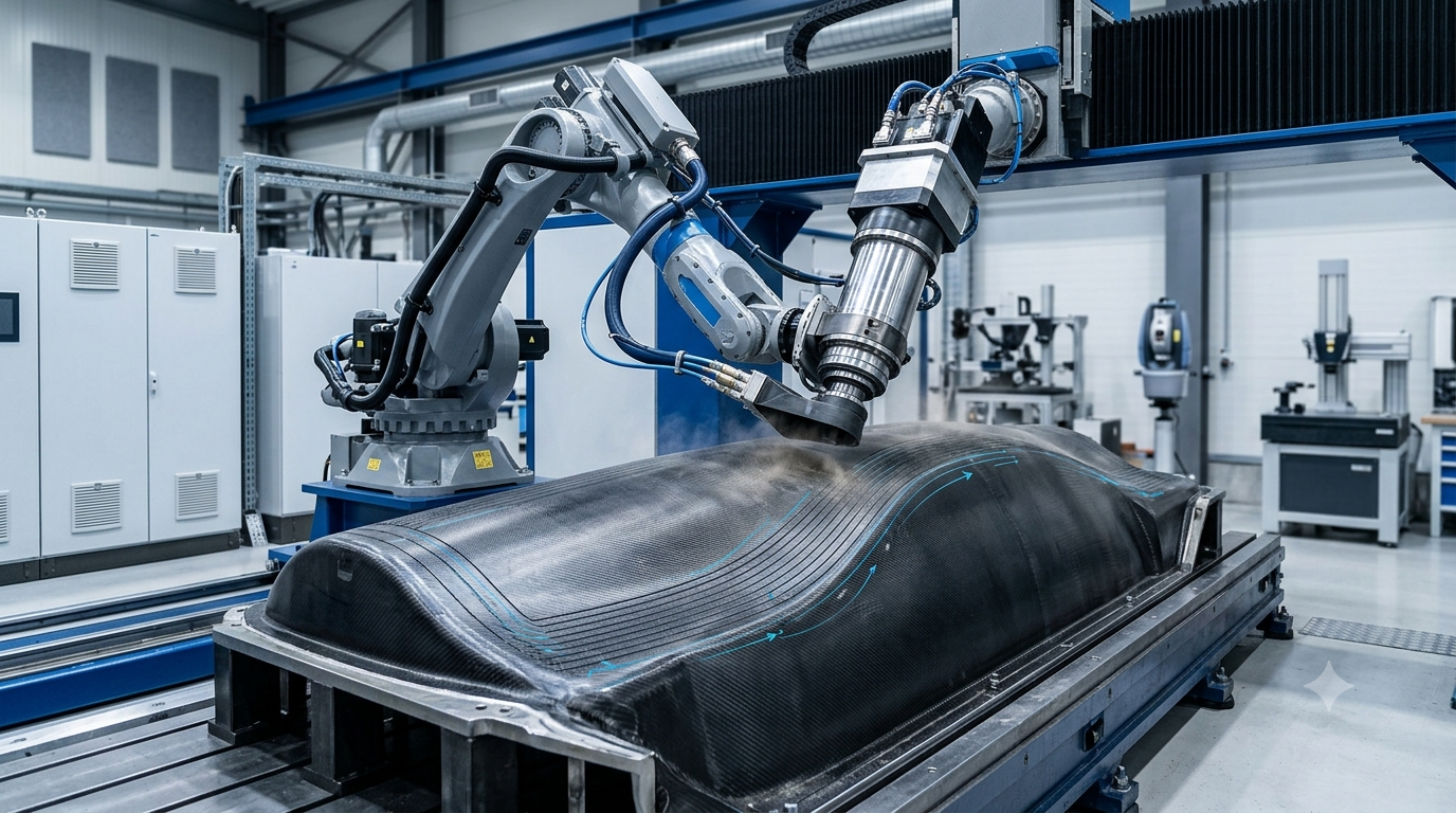
Composites
Composite machining often requires stable tool engagement, controlled vibration, and clean edge quality. If motion dynamics are unstable, the result can include surface irregularity, edge damage, or inconsistent finishing quality.
Aluminum
Aluminum requires a careful balance between spindle speed, feed rate, tool geometry, and robot stiffness. If acceleration and jerk are not controlled, chatter marks or inconsistent surface patterns may appear during finishing operations.
Plastics and Tooling Board
Plastics and tooling board may be more forgiving than metals, but they still require consistent motion. Poor trajectory smoothing can leave visible marks on large surfaces, especially when parts are painted, coated, polished, or used as molds.
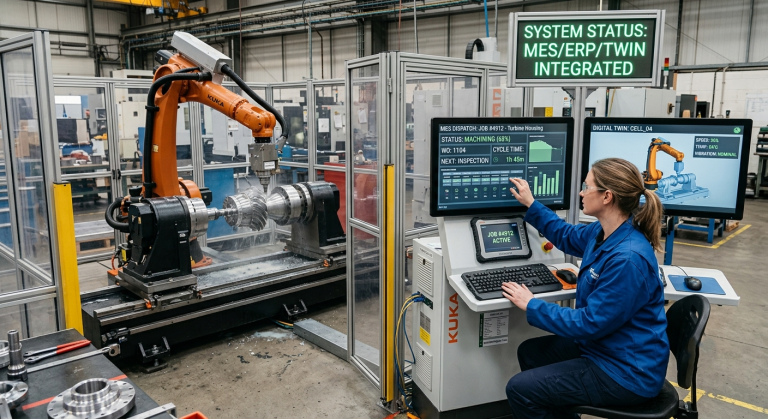
Why Integration Strategy Is Critical
The solution is not simply to reduce the feed rate. A slow robotic milling cell can still produce poor results if the spindle, toolpath, fixture, robot posture, and workpiece support are not correctly engineered.
Successful control of robot dynamics in robotic milling requires coordination between the robot controller, spindle system, CAM software, fixturing strategy, and machining parameters.
A properly designed robotic milling cell integrates several technical elements:
- High-speed spindle selection and mounting
- Robot dynamic limits and workspace behavior
- CAM post-processor tuning
- Toolpath smoothing and blending strategy
- Structural reinforcement where required
- Workpiece clamping and support
- Material-specific cutting parameters
- Validation through test cuts and surface measurement
Only when these elements are aligned can robot dynamics in robotic milling be controlled consistently. The robot arm is only one part of the machining system. Surface quality depends on the complete cell.
Successful robotic machining projects depend on managing robot dynamics in robotic milling through coordinated optimization of hardware, software, tooling, and process parameters.
For broader robotics industry information, the International Federation of Robotics provides valuable insights into industrial robot technologies and manufacturing applications.
When Robot Dynamics Become a Constraint
Robotic milling is not suitable for every machining requirement. The technology becomes more difficult when the process requires very tight tolerances, aggressive cutting forces, unstable fixturing, long tools, or machining positions where the robot has reduced stiffness.
Large parts also create additional challenges because the robot may need to work across a wide workspace. As posture changes, rigidity and dynamic response can change as well. This is why surface roughness should be measured across different robot positions, not only in the easiest area of the cell.
Robot dynamics can also become a constraint when the workpiece itself is flexible. If the part moves, vibrates, or deforms during machining, the robot cannot compensate through motion control alone. In these cases, fixture design and part support become as important as the robot program.
Technical Checklist Before Launching Production
Before validating a robotic milling process, engineering teams should use a structured checklist. The purpose is not only to confirm that the robot moves correctly but also to verify that the complete cell can produce the required surface quality under production conditions.
- Has acceleration been optimized for the material type?
- Has jerk limitation been configured and validated?
- Has toolpath smoothing been tested during real cutting?
- Has the CAM post-processor been tuned for robotic milling?
- Is structural stiffness acceptable across the full workspace?
- Has the spindle been selected for the material and tool size?
- Is the workpiece clamped and supported correctly?
- Has surface roughness been measured in different robot postures?
- Have finishing passes been validated separately from roughing passes?
- Has dimensional accuracy been checked after surface finish validation?
Robot Dynamics Are a Design Variable
Robot dynamics are not automatically a weakness. They are technical variables that must be understood, modeled, tested, and controlled during integration.
When properly engineered, large-format robotic milling cells can achieve consistent surface quality across extended toolpaths. The difference lies in integration depth: spindle selection, robot posture planning, CAM tuning, path blending, fixture design, and production validation.
For manufacturers comparing robotic milling with gantry CNC systems, the correct question is not whether one technology is always better. The correct question is whether the robotic cell can meet the required surface finish, tolerance, flexibility, and production volume for the specific application.
By understanding robot dynamics in robotic milling, manufacturers can improve surface consistency, reduce vibration-related defects, and achieve more predictable machining results.
Many robot manufacturers, including KUKA Robotics, publish technical resources related to robotic machining, motion control, and system integration.
FAQs
Do robots always produce a worse surface finish than CNC machines?
No. Robots do not always produce a worse surface finish. With proper tuning, integration, spindle selection, fixturing, and toolpath strategy, robotic milling can meet demanding industrial requirements in suitable applications.
Should acceleration always be reduced for a better finish?
Not necessarily. Lower acceleration may help in some cases, but controlled acceleration and optimized jerk parameters are usually more important than simply reducing speed.
Does robot posture influence surface finish?
Yes. Robot stiffness changes across the workspace. This means surface finish can vary depending on the robot posture, tool orientation, cutting direction, and distance from the robot base.
How does spindle speed interact with robot dynamics?
Spindle speed affects cutting behavior, but it must be matched with feed rate, tool geometry, material type, and robot stiffness. High spindle speed alone does not guarantee good surface quality.
Can CAM software compensate for dynamic limitations?
CAM software can help by improving toolpath strategy, smoothing, and post-processing, but it cannot solve poor fixturing, unstable workpieces, excessive cutting forces, or an unsuitable robot configuration.
Is robotic milling suitable for large-format machining?
Yes, robotic milling can be suitable for large-format machining when the required accuracy, surface finish, material, toolpath, and cell design are aligned. It should be validated through test cuts before production approval.
Robotic Hi-Tech Solutions is a European robotic integrator specializing in large-format robotic milling cells using KUKA, ABB, and FANUC robots equipped with high-speed spindles.
If surface quality and dynamic control are critical to your project, our engineering approach helps evaluate robot dynamics, spindle integration, toolpath strategy, fixture stability, and production performance before launch.