English
 Italiano
 Українська
 Русский
 Español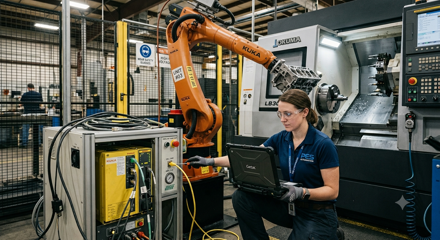

To connect a robot to a CNC machine, the two systems must exchange clear commands, status signals, safety conditions, and fault information. In a basic machine-tending cell, this may be handled through discrete inputs and outputs coordinated by M-codes. More advanced systems may also use an industrial network, a PLC, OPC UA, or a combination of these technologies.
The correct architecture depends on what the robot must do. Loading and unloading normally require deterministic handshaking between the robot, CNC controller, machine doors, chuck or fixture, and safety system. Production monitoring has different requirements and may use OPC UA or MTConnect to make machine data available to supervisory software.
This article explains how M-codes initiate automation sequences, how PLC handshakes prevent conflicting movements, and where OPC UA and MTConnect fit into the system. It also identifies the information that should be confirmed before integration. These technologies are not interchangeable: each serves a different control, communication, or monitoring purpose.
What Is Required to Connect a Robot to a CNC Machine?
Control, Status, and Safety Are Separate Functions
A reliable connection must coordinate three functions. The control layer requests actions such as opening a door or starting a machining cycle. The status layer confirms conditions such as cycle complete, door open, fixture released, or robot clear. The safety layer stops hazardous motion when protective conditions are not satisfied.
These functions should not be treated as one undifferentiated data exchange. A standard communication message may report that a door is closed, but a safety-rated interlock may still be required to confirm that hazardous motion is permitted. The required safety architecture depends on the cell design, risk assessment, equipment, and applicable regulations.
Determine Which Controller Coordinates the Sequence
One system must coordinate the operating sequence. In a simple installation, the CNC programmable machine controller may communicate directly with the robot. In a larger cell, a separate PLC may manage the robot, CNC machine, part feeder, inspection equipment, doors, fixtures, and auxiliary devices.
The coordinator should define which device can issue each command and what confirmation is required before the next action. Without this ownership, the robot and CNC may wait indefinitely for each other or respond incorrectly after a fault or manual intervention.
How M-Codes Control Robot-CNC Communication
M-Codes Trigger Machine-Specific Auxiliary Actions
M-codes are CNC program instructions used for auxiliary machine functions. Some functions are standardized or widely recognized, while others are assigned by the machine builder or configured for a particular application. Depending on the CNC controller, machine builder, PLC, or PMC program, and installed options, a configured M-code may be used to request robot loading, unloading, inspection, cleaning, or another external operation. The available functions and configuration method must be confirmed in the documentation for the specific machine.
When the CNC program reaches the configured M-code, the controller may activate an internal bit, PLC output, fieldbus variable, or physical output. The robot or cell PLC receives the request and begins the corresponding sequence. The CNC usually waits until it receives a completion signal before continuing the part program.
A Command Must Be Paired With Confirmation
An M-code alone does not prove that the requested action occurred. The sequence should include acknowledgements and condition checks. For example, a load request may require confirmation that the CNC cycle has stopped, the spindle is stationary, the machine door is open, the fixture is released, and the robot is authorized to enter.
After placing the part, the robot confirms that it has completed the operation and moved to a defined clear position. The CNC can then clamp the part, close the door, verify the required conditions, and begin machining. Each transition should occur only after the expected confirmation is received.
Using a PLC and Handshake Signals
Discrete Signals Provide Simple Deterministic States
Discrete inputs and outputs remain practical for basic robot-CNC handshaking. Typical signals include robot request, CNC cycle complete, door open, fixture open, robot in machine, robot clear, loading complete, unloading complete, cycle start permission, and fault reset permission.
The exact signal list varies by controller and cell design. Signal names should describe confirmed physical or logical states rather than vague commands. For example, “robot clear of machine” provides more useful information than a general “robot done” signal.
Networked I/O Can Reduce Physical Wiring
Industrial Ethernet and fieldbus systems can transmit the same logical signals without assigning an individual wire to every state. The robot controller, CNC, PLC, and remote I/O stations may exchange mapped bits and data words over a supported network.
Networked communication does not remove the need for a documented handshake. Engineers must still define signal direction, normal state, timeouts, reset behavior, communication-loss response, and the conditions required to advance each step. Safety functions must use equipment and architectures suitable for the required safety performance.
Where OPC UA Fits Into CNC Robot Integration
OPC Unified Architecture is an industrial interoperability framework that supports structured information exchange between devices, software, and enterprise systems. Depending on the equipment implementation, it can expose machine states, production values, alarms, operating modes, program information, and other variables through a standardized client-server architecture.
In a robot-CNC cell, OPC UA may connect the CNC or PLC with supervisory systems, dashboards, manufacturing execution systems, databases, or higher-level orchestration software. Its information models and security mechanisms make it more suitable for structured data exchange than a collection of undocumented controller registers.
OPC UA should not automatically replace the real-time handshake used for loading and unloading. Whether it can participate in control depends on the controller, software implementation, update requirements, network design, validation, and risk assessment. Time-critical machine coordination is often retained in the CNC PLC, robot controller, or cell PLC.
Where MTConnect Fits Into the Architecture
MTConnect provides a common semantic model for manufacturing-equipment data. An MTConnect agent can make contextualized information available to applications, including operating status, execution state, conditions, controller mode, and selected process values supported by the implementation.
Its principal role is data collection and monitoring rather than commanding machine motion. A manufacturer may use MTConnect to observe CNC utilization, detect downtime categories, collect alarms, or combine information from different machine tools in one production-monitoring platform.
MTConnect can complement the robot handshake, but it should not be treated as the direct replacement for M-code logic or PLC sequencing. The robot still requires confirmed permissions and completion states. MTConnect data can help analyze whether the completed cell is operating as intended and where production losses occur.
OPC UA, MTConnect, and M-Codes Serve Different Purposes
M-codes and PLC signals are normally closest to the operating sequence. They trigger actions and confirm that equipment has reached the state required for the next step. OPC UA provides a broader framework for structured and potentially bidirectional information exchange. MTConnect standardizes manufacturing data so that monitoring applications can interpret it consistently.
A cell may therefore use all three. An M-code requests unloading, the PLC manages the robot-CNC handshake, OPC UA exchanges production or recipe information with supervisory software, and MTConnect provides machine-status data for monitoring. The technologies should be selected according to the function rather than applied as competing alternatives.
Some CNC and robot manufacturers also provide vendor-specific methods for coordinating both systems. For example, this overview of G-codes for programming FANUC CNC robots explains one manufacturer-specific approach to linking CNC and robot operation. Availability depends on the selected controller, software, and integration package.
Eight Checks Before Implementing the Connection
- Confirm available controller interfaces. Identify the CNC model, software version, robot controller, PLC options, I/O capacity, supported industrial networks, OPC UA availability, and MTConnect support.
- Define the sequence step by step. Document every state from machining completion through door opening, unloading, loading, clamping, robot clearance, door closing, and cycle restart.
- Create an I/O and data map. Record each signal, address, direction, description, normal state, valid operating mode, and source controller.
- Separate standard and safety signals. Identify which conditions are operational information and which must be handled by safety-rated devices, controllers, and circuits.
- Specify acknowledgement rules. Pair each command with confirmation and prevent either controller from advancing when the expected state is missing.
- Set timeout and fault responses. Define what occurs when a door, fixture, robot, network, or CNC does not reach the requested state within the permitted sequence time.
- Plan manual and recovery modes. Establish how authorized personnel can recover a dropped part, interrupted cycle, communication fault, or partial sequence without bypassing safeguards.
- Validate every operating condition. Test automatic production, manual operation, restart, power recovery, emergency stops, access events, communication loss, rejected parts, and equipment faults.
Safety and Validation Requirements
The robot and CNC must be integrated as one machine system rather than assessed as unrelated equipment. Hazards can arise from robot movement, spindle rotation, tool breakage, clamping devices, automatic doors, ejected material, unexpected restart, and access during recovery.
The risk assessment should define safeguarding, access control, safe stopping, restart prevention, operating modes, fault recovery, and validation. The applicable requirements depend on the country and installation. The current ISO 10218-2 standard for industrial robot applications and robot cells is a relevant technical reference, but it does not replace a project-specific compliance assessment.
Communication testing must include abnormal events, not only successful automatic cycles. Disconnecting a network, withholding a completion signal, opening an access point, changing operating mode, or stopping one controller should cause a defined response. The system should not continue because a stale status bit remains active.
Frequently Asked Questions
Can a robot connect directly to a CNC machine?
Yes, when both controllers have compatible I/O or network interfaces and can manage the complete handshake. A separate PLC is often used when several devices, complex sequencing, or centralized diagnostics are involved.
Does every CNC machine support custom M-codes?
No. Available M-codes and configuration methods depend on the CNC controller, machine builder, installed options, and PLC program. The machine documentation and supplier should be checked before designing the interface.
Can OPC UA control the robot loading cycle?
It may exchange commands in some architectures, but suitability depends on the implementation and timing requirements. Deterministic loading sequences are commonly managed through the CNC PLC, robot controller, or cell PLC.
Is MTConnect a control protocol?
MTConnect is primarily used to expose standardized manufacturing-equipment data to monitoring and software applications. It is not normally used to command robot or CNC motion.
What happens if the robot loses communication with the CNC?
The response should be defined during integration. The sequence normally stops, commands are cleared or held safely, and restarting requires verified equipment states rather than assuming the previous step was completed.
Are standard I/O signals enough for machine tending?
They can be sufficient for a straightforward cell when all required states, acknowledgements, diagnostics, and safety functions are addressed. More complex systems may need networked data and a coordinating PLC.
Should the CNC or robot control the automatic sequence?
Either may coordinate a simple sequence, but one controller must have clearly defined ownership. Cells with multiple machines or auxiliary devices generally benefit from centralized PLC coordination.
How should the completed connection be tested?
Test normal cycles, all operating modes, timeouts, signal conflicts, communication loss, emergency stops, access events, power restoration, rejected parts, and recovery from every interrupted sequence.
Building a Reliable Robot-CNC Interface
To connect a robot to a CNC machine reliably, begin with the operating sequence rather than the communication technology. Define every command, confirmation, safety condition, fault response, and recovery action before assigning I/O addresses or network variables.
M-codes can initiate CNC automation requests, PLC handshakes can coordinate deterministic actions, OPC UA can provide structured system integration, and MTConnect can support production monitoring. For assistance evaluating controller compatibility and the architecture of a specific machining cell, contact Robotic Hi-Tech Solutions with the CNC model, robot controller, required process, and available interfaces.