English
 Italiano
 Українська
 Русский
 Español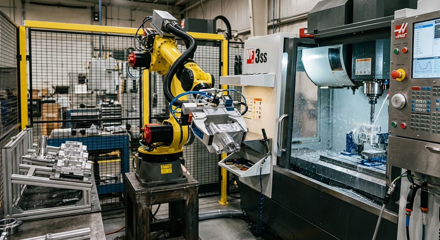

End-of-arm tooling for machining automation must hold or manipulate a part without allowing unwanted movement while the robot accelerates, changes orientation, loads a machine, or interacts with the process. Preventing slippage and vibration therefore depends on more than selecting a gripper with enough nominal force. The complete tool, part, robot motion, contact surfaces, payload, center of gravity, and process forces have to be considered together.
Slippage usually begins when the forces trying to move the workpiece exceed what the gripping arrangement can resist. Vibration has a different mechanism. It can develop from structural compliance, robot motion, machining forces, long tool extensions, loose connections, or unfavorable robot configurations. In some applications, both problems occur together because vibration reduces the stability of the contact between the gripper and the part.
A reliable design starts by defining what the end effector must do during every stage of the cycle. Engineers can then evaluate gripping method, jaw geometry, stiffness, mounting, robot payload limits, motion profile, sensing, and validation under realistic operating conditions.
What must end-of-arm tooling control?
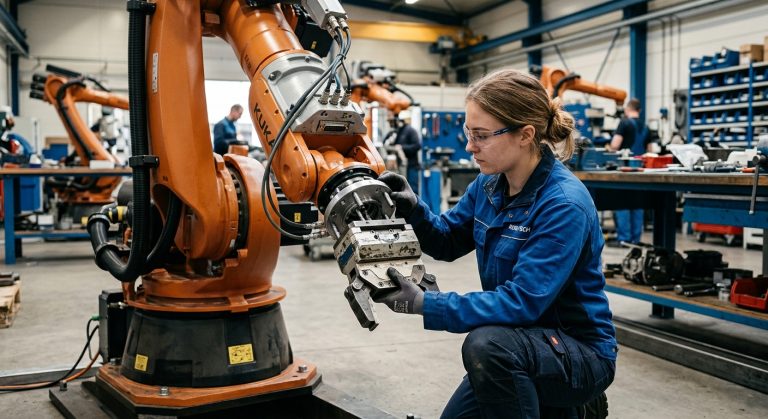
End-of-arm tooling includes the equipment attached to the robot wrist to perform the application. In machine tending, this may be a mechanical or pneumatic gripper. In robotic machining, the end effector may instead carry a spindle, deburring tool, drilling unit, or other process equipment. Adapters, sensors, valves, cables, and other wrist-mounted components also affect the mechanical system.
Grip force is only one part of holding stability
A gripper must create enough usable holding capacity for the actual part and motion. The required capacity depends on factors such as workpiece mass, orientation, acceleration, contact geometry, friction conditions, and external forces. A catalog gripping-force value alone does not demonstrate that a particular workpiece will remain secure throughout a robot cycle.
Stiffness affects position and vibration
The mechanical path from the robot wrist to the workpiece or cutting tool should also be sufficiently stiff for the process. Flexibility in brackets, adapters, gripper fingers, spindle mounts, or other components can allow deflection under load. In robotic machining, research has shown that end-effector and robot stiffness influence dynamic behavior and vibration during material removal.
Why can a workpiece slip from a robot gripper?
Slippage occurs when the gripping arrangement cannot resist the forces acting on the workpiece. These forces are not necessarily constant. A part that remains secure while the robot is stationary may behave differently when the robot accelerates, decelerates, rotates the wrist, or changes the orientation of the workpiece relative to gravity.
Contact geometry and surface condition matter
The way the jaws contact the part affects how forces are transmitted. Jaw shape, contact area, part geometry, surface condition, and the material at the interface can influence holding performance. Coolant, oil, chips, dust, or other contamination may also change contact conditions, so validation should reproduce the real production environment rather than relying only on a clean test part.
Acceleration changes the load on the grip
Robot motion creates inertial forces. Faster acceleration or an abrupt change in direction can increase the forces that the end effector must resist even though the workpiece mass has not changed. Motion profiles should therefore be evaluated together with the gripping system rather than treating robot speed and gripper selection as independent decisions.
Why does vibration appear in machining automation?
Vibration can originate in several parts of an automated machining system. Possible sources include cutting forces, spindle or tool imbalance, robot structural compliance, flexible end-effector components, part fixturing, joints between adapters, and rapid robot motion. Identifying the source is important because increasing gripper force will not correct every vibration problem.
Robot configuration can change dynamic behavior
An articulated robot does not have identical stiffness in every pose and direction. Research into robotic milling has demonstrated that vibration behavior can vary with robot configuration and machining direction. A process that behaves acceptably in one area of the working envelope may therefore require separate validation when the robot posture changes substantially.
Tooling geometry also matters. Long or unnecessarily flexible extensions between the wrist and the working point can increase deflection. Where possible, the mechanical design should keep the load path compact while still providing the clearance and reach required by the machine and workpiece.
How should end-of-arm tooling for machining automation be designed?
The design should begin with the real operating loads rather than with a preferred gripper model. Engineers need to define the workpiece, robot trajectory, orientations, required reach, machine interface, expected contamination, and any forces applied while the end effector is holding or processing the part.
The complete wrist load must also be evaluated against the robot manufacturer’s permitted loading conditions. This means accounting for the end effector and attached equipment, not only the workpiece. Center of gravity and inertia can be important because two assemblies with the same total mass can load the robot wrist differently when their mass is distributed differently.
For additional context on machining cells, robot integration, and related applications, the Robotic Hi-Tech Solutions technical articles on robotic machining and automation provide related information about industrial robot applications.
Eight checks before approving an end effector
A structured engineering review can identify problems before the tooling reaches continuous production. The following eight checks address both holding stability and vibration.
- Calculate the complete wrist load. Include the gripper or process tool, adapters, brackets, sensors, valves, cables, or other supported equipment and the workpiece when applicable.
- Check center of gravity and inertia. Compare the complete assembly with the robot manufacturer’s permitted load data instead of checking mass alone.
- Review the gripping principle. Confirm how the jaws or other holding elements resist gravity, robot acceleration, orientation changes, and relevant external process forces.
- Inspect contact surfaces. Evaluate jaw geometry, contact location, workpiece tolerances, and realistic conditions involving coolant, oil, chips, dust, or surface variation.
- Minimize unnecessary flexibility. Examine long fingers, thin brackets, extended adapters, unsupported components, and bolted interfaces that can deflect under load.
- Test realistic robot motions. Validate acceleration, deceleration, wrist rotation, approach moves, transfer paths, and the most demanding orientations used in production.
- Check the entire mechanical chain. Determine whether movement comes from the gripper, workpiece, robot, fixture, spindle, toolholder, cutting tool, or another interface before changing the design.
- Validate abnormal conditions. Define how the system detects or safely handles conditions such as an incorrectly positioned part, incomplete grip, loss of pressure, or process interruption.
How should slippage and vibration be validated?
Validation should reproduce the actual operating cycle as closely as practical. Static holding tests alone cannot reproduce every dynamic load generated during robot motion. Tests should include the expected workpiece range, robot poses, orientations, accelerations, tooling configuration, and environmental conditions.
Movement should also be investigated at its source. If a part shifts relative to the gripper jaws, the problem differs from a tool vibrating because of structural compliance. Likewise, movement at an adapter plate requires a different corrective action from machining chatter generated by the interaction between cutting forces and system dynamics.
When vibration is related to material removal, process parameters and robot configuration may need to be evaluated together. Cutting behavior in robotic machining depends on the mechanical dynamics of the robot-tool-workpiece system, so there is no universal adjustment that eliminates vibration in every cell.
What safety factors must be considered?
The end effector is part of the industrial robot system and must be included in the application risk assessment. Hazards can arise from the robot motion, the workpiece, the end effector itself, unexpected release of a part, stored energy, machining equipment, and interaction with other machinery in the cell.
The OSHA Technical Manual chapter on industrial robot systems and robot system safety identifies end effectors as components of robot systems and describes risk assessment and safeguarding considerations. Applicable requirements depend on the installation, jurisdiction, machinery, and tasks performed, so the relevant current standards and regulations must be reviewed for each project.
When should the tooling design be reviewed by an integrator?
An integration review is useful when the end effector must combine demanding payload, restricted machine access, multiple workpiece variants, process forces, complex sensing, or synchronization with CNC equipment. The objective is to confirm that the robot, tooling, machine interface, motion strategy, and safety functions have been designed as one system.
For a machining automation project that requires evaluation of robot reach, end-of-arm tooling, machine interaction, or cell architecture, companies can contact Robotic Hi-Tech Solutions to discuss the application requirements and determine what engineering information is needed for a technical assessment.
FAQ
What causes a robot gripper to lose a workpiece?
A workpiece can move when the gripping arrangement cannot resist gravity, inertia, external loads, or changes in contact conditions. The exact cause should be established before changing grip force or robot speed.
Does higher gripping force always prevent slippage?
No. Holding stability also depends on jaw geometry, contact conditions, workpiece strength, motion, orientation, and external forces. Excessive force may also be unsuitable for parts that can deform or become damaged.
Can robot acceleration cause a part to slip?
Yes. Acceleration and deceleration create inertial loads that the gripping system must resist. A part that is secure while stationary should therefore also be tested during representative robot movements.
Can long gripper fingers increase vibration?
Long or flexible fingers can contribute to deflection because they extend the load path from the gripper body to the workpiece. Their effect depends on geometry, material, loading, and the application.
Does robot pose affect machining vibration?
It can. The stiffness and dynamic response of an articulated industrial robot vary with configuration and loading direction, which is one reason machining conditions should be validated across the poses used by the process.
Should payload calculations include the gripper?
Yes. Robot loading evaluation should consider the complete load supported at the wrist, including the end effector, adapters, attached components, and handled workpiece where applicable.
Can coolant or oil affect gripping reliability?
They can change the conditions at the contact interface. If contamination is expected in production, gripping tests should represent those conditions instead of evaluating only clean, dry components.
How can engineers tell whether vibration comes from the robot or tooling?
The mechanical system should be inspected and tested systematically. Comparing behavior across robot poses, tooling configurations, process states, and stationary versus cutting conditions can help isolate whether movement originates in the robot, end effector, fixture, spindle, tool, or workpiece.