English
 Italiano
 Українська
 Русский
 Español
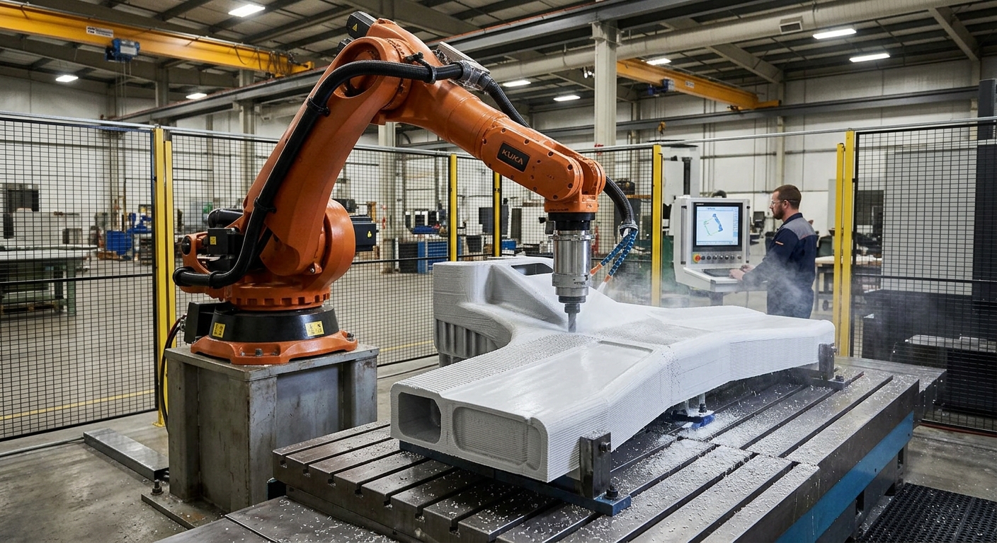

How much machining allowance should be left on robotically printed parts? The answer depends on the material, printing accuracy, component geometry, and required surface finish. Machining allowance is the extra material intentionally added to a printed surface so that a finishing operation can remove irregularities and achieve the specified dimensions.
In large-format robotic 3D printing, deposited layers rarely produce perfectly uniform surfaces. Bead variations, thermal contraction, and geometric distortion can change the final shape. Therefore, selecting a fixed allowance without measuring the actual printing process may leave insufficient material for finishing or create unnecessary machining work.
A reliable approach starts with the final CAD geometry, measured printing deviations, and the capabilities of the milling system. Engineers should evaluate the material remaining after cooling, the available cutting access, and the required tolerances. This article explains how to establish, calculate, and validate machining allowance without relying on unsupported universal values.
What determines machining allowance in robotic 3D printing?
Machining allowance is measured between the intended finished surface and the corresponding printed surface. Its purpose is to provide enough material for the cutting tool to produce the required final geometry.
Why printed geometry differs from CAD geometry
Robotic extrusion creates surfaces from overlapping material beads. Their dimensions depend on extrusion flow, travel speed, nozzle geometry, and material behavior. These variables influence how closely the deposited structure follows its digital model.
The relationship between bead dimensions and deposited geometry is explained in the article on controlling extrusion bead width and layer height. Understanding these variations helps engineers estimate the material that subsequent machining must remove.
Why a universal allowance is unreliable
Two parts printed with the same robot may require different finishing allowances. Their geometry, orientation, deposition strategy, and thermal history can produce different deviations. Consequently, allowance should be established for each representative process and critical surface.
How material properties influence machining allowance
Material behavior affects both the final printed geometry and its response to cutting. Thermoplastic polymers, reinforced polymers, and metal deposits have different thermal and mechanical characteristics. Their finishing strategies must therefore be evaluated separately.
Thermal contraction and dimensional stability
Thermoplastic components can contract during cooling. Uneven temperature distribution may also cause warping, particularly in large structures with varying wall thicknesses. The resulting deviation must be evaluated after the part reaches the condition specified for inspection.
The article on interlayer cooling in large-format polymer printing examines how thermal conditions influence shape retention and dimensional stability. These effects should be considered before establishing the machining envelope.
Reinforced polymers introduce additional considerations. Fiber content, orientation, and material formulation can influence shrinkage and cutting behavior. Engineers should confirm suitable tooling and machining conditions through material-specific trials rather than transferring settings between different formulations.
How part geometry changes the required allowance
A uniform offset may appear convenient during CAD preparation, but it does not necessarily provide adequate finishing stock across an irregular printed surface.
Curved walls, corners, inclined surfaces, and unsupported regions can experience different deposition behavior. Local bead accumulation may increase material thickness, while distortion can move other regions inside the intended finished boundary.
Large components also introduce measurement and positioning challenges. Small angular deviations can produce substantial dimensional differences over long distances. Engineers should therefore inspect critical regions individually instead of relying only on average dimensional error.
How to calculate machining allowance from measurements
The calculation should begin with a comparison between the measured printed surface and the required finished geometry. A suitable coordinate reference must be established before interpreting deviations.
For an external surface, a practical starting estimate is the greatest measured material deficit relative to the intended finishing stock, combined with an appropriate margin for measurement uncertainty and process variation. The resulting allowance must still respect structural and machining constraints.
For example, consider a wall whose printed surface varies around the intended geometry. Engineers should identify its most inward deviation, verify whether sufficient material remains behind that location, and determine whether the finished contour can be produced without exposing internal voids.
This assessment must distinguish excess surface material from missing stock. Milling can remove an outward protrusion, but it cannot restore material where the printed structure falls inside the required finished boundary.
How printing and milling should be planned together
Hybrid manufacturing combines additive deposition with subtractive finishing. Both operations should reference the same final geometry and an established coordinate system.
Maintain consistent reference points.
Datums are reference features or surfaces used to locate and measure a component. They should remain accessible throughout printing, inspection, and machining whenever possible.
Changing the workpiece position without updating its coordinate reference can introduce alignment errors. Similarly, clamping a flexible printed component may temporarily change its shape and affect the finished dimensions after release.
Workholding stability also influences machining performance. The article on robotic milling fixturing and vibration control explains why supporting the component correctly matters during material removal.
How cutting conditions affect the selected allowance
Machining allowance must be compatible with the actual finishing equipment. Robot stiffness, spindle configuration, cutter geometry, tool accessibility, and material behavior influence how much stock can be removed effectively.
Separate roughing from finishing
Roughing removes larger amounts of material to approach the required geometry. Finishing removes the remaining stock under conditions selected for dimensional accuracy and surface quality.
For complex printed surfaces, dividing removal into controlled stages may reduce abrupt changes in cutting load. However, the cutting strategy must reflect the machine’s capabilities and the component’s stiffness.
Excessive allowance increases the material removal required. Insufficient allowance may leave visible deposited layers or unmachined regions. Neither outcome can be corrected reliably through cutting parameters alone.
How to verify the allowance before production
Validation should combine dimensional inspection with controlled machining trials. Measurements taken only after finishing cannot fully explain whether a deviation originated during printing, positioning, or material removal.
Use representative printed test features
Test features should reproduce the relevant wall angles, bead patterns, corners, and material thicknesses of the production component. Measuring these features provides evidence for refining the allowance.
When assessing polymer parts, engineers may also consult ISO/ASTM 52924:2023, which addresses the classification of properties for additively manufactured polymer parts. It does not prescribe a universal machining allowance.
Inspection results should include local dimensional deviations, remaining wall thickness, and the actual material removed. Repeated trials help determine whether the selected allowance remains suitable under normal process variation.
Eight checks before approving machining allowance
Before releasing a printed component for finishing, engineering teams should complete the following checks:
- Confirm finished dimensions: Identify the surfaces requiring machining and their specified dimensional tolerances.
- Inspect printed geometry: Compare measured surfaces against the finished CAD model using consistent datums.
- Evaluate local deviations: Identify regions with insufficient stock, excessive buildup, or significant distortion.
- Check material stability: Verify that cooling, curing, or other relevant conditioning has been completed before inspection.
- Verify minimum wall thickness: Ensure material removal will not compromise required structural dimensions.
- Review cutter accessibility: Check tool reach, orientation, collision clearance, and robot configurations.
- Validate the machining sequence: Establish suitable roughing and finishing operations through representative trials.
- Document inspection results: Record dimensional deviations, actual stock removal, and acceptance criteria for future builds.
These checks establish a documented basis for allowance selection. When results show insufficient material on a critical surface, the printing strategy or nominal printed geometry must be revised before production continues.
For manufacturers developing combined printing and milling processes, Robotic Hi-Tech Solutions can review the application requirements, including component geometry, robot configuration, workholding, and finishing objectives.
Frequently Asked Questions
How much machining allowance is normally required?
There is no universal value. The required allowance depends on measured printing deviations, material behavior, finishing tolerances, and machining capabilities. Representative trials should establish the applicable range.
Can the same allowance be used on every surface?
Not necessarily. Different orientations, geometries, and deposition conditions can produce different deviations. Critical surfaces may require separate stock calculations.
Does increasing machining allowance improve accuracy?
Not automatically. Additional material provides more finishing stock but can increase cutting time and forces. Accuracy also depends on calibration, workholding, tooling, and measurement.
Should printed parts cool before measuring allowance?
For thermoplastic components, measurements should be taken after the specified cooling or conditioning stage. This reduces uncertainty associated with ongoing dimensional changes.
Can machining remove every visible printing defect?
No. Machining can remove accessible surface irregularities when sufficient sound material remains. Internal voids, inadequate bonding, and material deficits require separate evaluation.
Is machining allowance different for reinforced polymers?
It can be. Reinforcement affects material properties, cutting behavior, and potentially dimensional stability. Allowance and machining parameters should be validated for the specific formulation.
How can engineers reduce excessive machining stock?
Improving extrusion consistency, controlling thermal conditions, and validating robot positioning can reduce dimensional variation. Measurements should confirm improvements before reducing the allowance.
When should machining allowance be recalculated?
Reassess it after significant changes to material, nozzle configuration, extrusion settings, part geometry, build orientation, or finishing requirements. New measurements should support the revised value.