English
 Italiano
 Українська
 Русский
 Español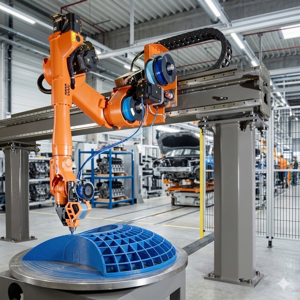

A rotary positioner can improve robotic 3D printing when rotating the part gives the robot better access, more useful nozzle orientations, or a more practical motion path than moving the robot alone. It is particularly relevant for multi-axis deposition, large components, curved surfaces, and parts that would otherwise force the robot into difficult joint configurations.
The main benefit is not simply that the workpiece can turn. A correctly integrated rotary positioner becomes another controlled axis in the manufacturing cell. It can reorient the component between deposition operations or move together with the robot when the controller, software, and process architecture support coordinated motion.
However, adding a rotary positioner also increases mechanical, programming, calibration, and safety requirements. It is useful only when its contribution to accessibility or process geometry justifies that added complexity. This article explains when a positioner helps, when a fixed platform may be preferable, and what should be verified before implementing one.
When Does a Rotary Positioner Improve the Printing Process?
A rotary positioner is most useful when part orientation limits the deposition strategy. An articulated robot already provides several degrees of freedom, but its joint range, reach, collision constraints, tooling geometry, and cable routing can prevent it from maintaining a suitable nozzle orientation throughout a complex build.
Coordinated robot and positioner motion
In a coordinated system, the robot and external axis are programmed as part of the same motion problem. Rotating the workpiece can allow the robot to remain in a more favorable posture while the required deposition point moves through space. This approach differs from simply stopping the process, indexing a table, and restarting from another fixed orientation.
Rotary motion can also help maintain access to different sides of a component. The broader role of external axes in additive cells is discussed in this RHS guide to robots for large-scale 3D printing, which covers rotary positioners as part of the complete system rather than as stand-alone equipment.
How Does Part Rotation Change Nozzle Accessibility?
Access and nozzle orientation
Some deposition paths require the nozzle to approach a surface from an angle instead of remaining vertical. Rotating the workpiece may make that orientation easier to achieve without excessive robot wrist movement. This can be useful for curved surfaces, inclined walls, non-planar layers, and deposition around cylindrical or approximately rotational geometries.
The positioner does not automatically create a valid printing strategy. The programmed nozzle direction must still be compatible with the material process, extruder geometry, surrounding equipment, previously deposited material, and the physical limitations of the robot.
Changing orientation can also affect bead formation because the relationship between gravity, the nozzle, and the receiving surface changes. Bead geometry therefore needs to be validated under the actual orientations used during production rather than inferred from tests performed only on a horizontal platform.
Can a Rotary Positioner Increase the Usable Build Envelope?
Build envelope versus robot reach
A positioner can increase the portion of a component that the robot can reach effectively without increasing the robot arm’s nominal reach. Instead of asking the arm to reach around a large object, the system can present another side of the part to the robot.
This distinction matters when evaluating cell layout. A rotary axis does not simply make the robot physically longer. It changes the relative position and orientation between the tool and workpiece, potentially bringing otherwise difficult regions into a more accessible part of the robot’s working envelope.
For very large parts, a positioner may also be combined with other external axes or a suitable robot mounting arrangement. Every additional axis, however, creates new requirements for simulation, collision checking, structural design, cable management, controls, and calibration.
Which Printing Applications Benefit Most?
Rotary positioners are particularly relevant when the geometry itself benefits from controlled workpiece rotation. Examples include deposition around cylindrical forms, curved tooling, large molds, architectural components, and parts requiring material placement on multiple faces.
They may also help when a multi-axis path needs to keep the extruder away from previously deposited material. Rotating the component can change the approach direction and provide clearance that would be difficult to obtain by robot wrist movement alone.
Process variables remain interconnected. Even when the positioner improves accessibility, robot speed, material output, layer spacing, and nozzle distance still influence the deposited result. The RHS article on extrusion bead width and layer height explains why motion and deposition parameters must be evaluated together.
When May a Rotary Positioner Not Be Necessary?
Fixed versus coordinated positioning
A positioner adds little value when the complete part can already be printed from a fixed platform using stable robot configurations and suitable nozzle orientations. For relatively simple planar builds, adding another controlled axis can create engineering work without solving a meaningful limitation.
An indexed approach may also be sufficient for some components. The positioner can rotate to a defined angle while printing is stopped, after which the robot performs another operation from the new orientation. This is mechanically and computationally different from continuous coordinated motion and may be adequate when uninterrupted deposition is not required.
The selection should therefore follow the geometry and process requirements. A rotary positioner should solve a specific reach, orientation, collision, or deposition problem rather than be included simply because the robot controller can support external axes.
How Does Calibration Affect a Rotary Positioner?
External-axis and tool calibration
Correct coordinate relationships are essential once the workpiece can move. The system must know how the positioner axis relates to the robot base, workpiece reference, and programmed geometry. Errors in these relationships can shift the real deposition path even when the digital toolpath appears correct.
Tool Center Point calibration remains equally important. When the extruder changes orientation, an incorrect TCP can make the physical nozzle move away from its intended point. The geometric consequences are explained in the RHS guide to extruder TCP calibration in robotic 3D printing.
Calibration should therefore be evaluated as a complete coordinate chain rather than by correcting one reference until a test part appears acceptable. Tool data, robot base data, workpiece coordinates, positioner geometry, and the physical mounting of the component must remain consistent with the programming model.
Eight Checks Before Adding a Rotary Positioner
Before selecting or programming a rotary axis, evaluate whether it solves a measurable limitation in the planned deposition process. The following checks help define the technical requirement before equipment is added to the cell.
- Identify inaccessible regions: determine which deposition paths cannot be reached reliably with the workpiece fixed.
- Check required nozzle orientations: establish whether rotating the component reduces difficult wrist orientations or provides a better deposition approach.
- Evaluate the complete moving load: consider the workpiece, fixture, build plate, deposited material, and any other mass supported by the positioner.
- Simulate robot and external-axis motion: examine reach, joint configurations, collisions, axis limits, and clearances throughout the planned build.
- Define the motion strategy: decide whether the application requires indexing between operations or coordinated movement during deposition.
- Verify coordinate calibration: establish how the positioner axis, workpiece frame, robot base, and extrusion TCP will be measured and maintained.
- Review cables and material delivery: check whether rotation can interfere with extruder cables, hoses, feeders, sensors, or other services.
- Validate representative deposition paths: test bead formation and dimensional behavior at the orientations and speeds expected in the real component.
What Safety and Integration Issues Change?
A rotary positioner introduces another source of powered motion into the robotic cell. The integration therefore needs to consider access to the moving workpiece and fixture, possible trapping or crushing locations, robot-positioner interactions, emergency stopping, operating modes, maintenance access, and process-specific hazards from the extrusion equipment.
ISO 10218-2:2025 addresses safety requirements for industrial robot applications and robot cells, including system integration, commissioning, operation, and maintenance. The required protective measures for a specific printing system must be determined through the applicable risk assessment and engineering process.
Mechanical integration also matters. The positioner, fixture, and supporting structure must suit the loads and motions created by the application. Programming capability alone does not establish that a particular mechanical arrangement is suitable for the intended component.
How Should You Decide Whether to Use a Rotary Positioner?
The decision should begin with the deposition path, not the positioner specification. Map the required tool positions and orientations, identify where the robot approaches its practical limitations, and determine whether rotating the workpiece removes those limitations without creating unacceptable process or integration problems.
A rotary positioner is justified when it produces a clear geometric or process advantage: better accessibility, more practical robot postures, controlled workpiece orientation, or a build strategy that cannot be achieved efficiently from a fixed platform. Its value is application-specific rather than universal.
For projects where robot reach, external-axis motion, extrusion equipment, or cell geometry must be evaluated together, manufacturers can contact Robotic Hi-Tech Solutions to discuss the application requirements and integration constraints.
FAQ
What is a rotary positioner in robotic 3D printing?
It is a powered external axis that rotates the workpiece or build platform. It can be used for indexing between printing operations or integrated into coordinated robot motion when the system supports that strategy.
Does a rotary positioner increase robot reach?
It does not increase the robot arm’s nominal reach. Instead, it repositions the component so different regions may become accessible within the robot’s existing working envelope.
Can the robot and positioner move at the same time?
They can in systems designed for coordinated external-axis motion. The controller, programming workflow, kinematic configuration, and application must support this type of synchronized movement.
Is a positioner required for non-planar robotic printing?
No. Some non-planar paths can be produced using the robot’s own axes. A positioner becomes relevant when workpiece rotation improves access, nozzle orientation, robot posture, or collision clearance.
Can a rotary positioner affect printing accuracy?
Yes. Errors in the positioner geometry, workpiece coordinates, tool calibration, mechanical mounting, or coordinate transformation can change the physical location of the deposited path.
Should the positioner rotate continuously during printing?
Not necessarily. Some applications benefit from simultaneous coordinated motion, while others only require the component to be indexed to several fixed orientations between deposition operations.
Does rotating the part change extrusion behavior?
It can. Rotation changes the orientation of the deposited material relative to gravity and may alter how the bead contacts and remains supported by the previous surface. Representative process testing is therefore necessary.
When is a fixed build platform preferable?
A fixed platform is generally simpler when the robot can already reach the complete deposition path with appropriate tool orientation, clearance, and joint configurations. In that situation, an additional axis may add complexity without providing a useful process advantage.