
One of the major advantages of robotic milling over gantry CNC systems is multi-axis flexibility. Industrial robots can machine vertically, horizontally, at inclined angles, or fully inverted.
However, orientation is not only a matter of geometric freedom. It directly affects structural loading, chip evacuation, surface quality, and process stability. Understanding these differences is essential when designing large-format robotic milling cells.
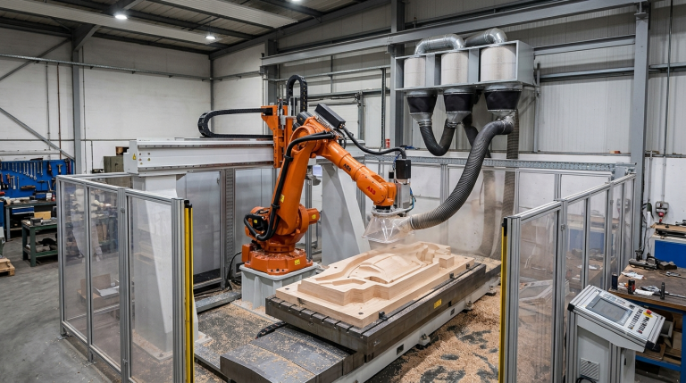
Vertical Milling Configuration
In a vertical milling configuration, gravity usually assists chip evacuation, tool loading is more predictable, and structural torque on the wrist axes is often easier to manage.
This configuration is commonly used when machining mold top surfaces, foam models, aluminum plates, and other parts where the tool can approach from above without complex access restrictions.
Advantages of vertical robotic milling
- More stable force distribution
- Better chip fall-off
- Reduced risk of chip accumulation around the tool
- Simpler extraction strategy in many applications
Limitations of vertical robotic milling
- Access to side walls may be restricted
- Large parts may require repositioning
- Undercuts or complex geometries may need additional robot orientations
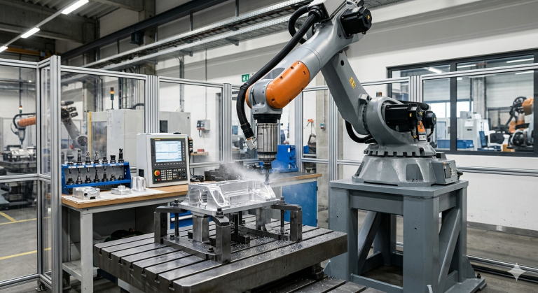
Horizontal Milling Configuration
When machining horizontally, chip evacuation becomes less dependent on gravity. Chips may accumulate on vertical surfaces, and the robot wrist axes may experience different torque patterns depending on tool angle, spindle weight, and cutting forces.
Horizontal robotic milling is often used for side-wall trimming, large structural panels, aerospace components, composite parts, and applications where the tool must approach the workpiece from the side.
This configuration usually requires optimized extraction systems, careful toolpath planning, and dynamic stiffness validation before production.
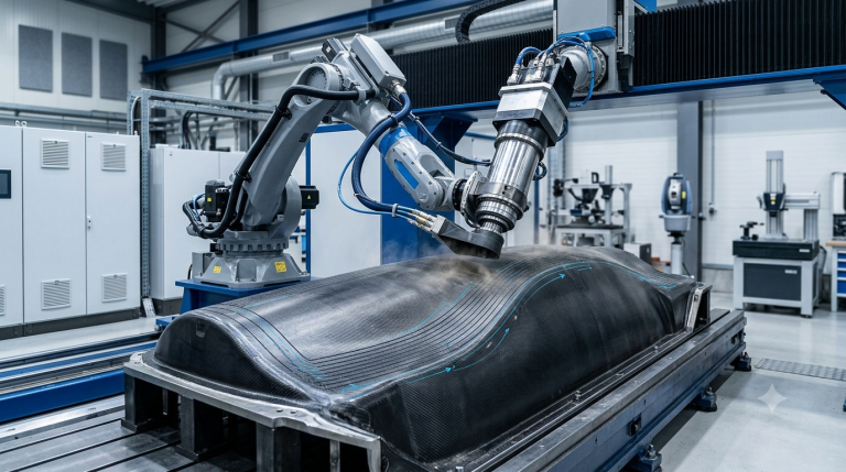
Inverted or Overhead Milling Configuration
In inverted robotic milling, the spindle works upward or overhead. This creates additional engineering challenges because chips can fall toward the tool, increasing the risk of debris recirculation and contamination near the cutting zone.
Structural considerations also become more critical. Wrist-axis loading, spindle inertia, robot posture, and deflection under cutting forces must be evaluated carefully before using an inverted strategy.
This configuration is typically justified when complex undercuts exist, part geometry requires full access, or repositioning the workpiece is impractical.
In robotic systems from KUKA, ABB, FANUC, and other major industrial robot manufacturers, payload and inertia modeling must be validated before approving overhead milling configurations.
Engineering Checklist for Orientation Strategy
Use this checklist before defining the final milling orientation strategy for a robotic cell.
- Has chip evacuation been tested for each machining orientation?
- Are wrist-axis torque limits verified under full load?
- Is surface quality validated during overhead passes?
- Are extraction systems adapted to each orientation?
- Is structural deflection measured during horizontal cuts?
- Is the CAM strategy adjusted for gravity influence?
- Has payload and inertia modeling been confirmed for the selected spindle and tooling?
Why Orientation Must Be Treated as an Engineering Variable
In robotic milling, orientation is both a process variable and a structural variable. Vertical machining often provides stability benefits because gravity supports chip evacuation and force distribution is easier to manage.
Horizontal and inverted machining can provide greater access flexibility, but they require additional engineering validation. Chip management, robot stiffness, spindle loading, surface finish, and toolpath strategy must all be reviewed before production.
To achieve surface quality and repeatability in large-format robotic cells, orientation-specific dynamics must be considered from the beginning of the cell design process.
For additional information about industrial robot applications, see OSHA’s robotics guidance
FAQ
Is vertical robotic milling always more stable?
In many cases, vertical robotic milling is more stable because chip evacuation is gravity-assisted and force distribution is easier to control. However, stability still depends on the robot model, spindle, tooling, material, fixture, and cutting parameters.
Does inverted robotic milling reduce accuracy?
Not inherently. Inverted milling can be accurate, but it increases structural demands and requires proper validation of robot stiffness, payload, inertia, chip evacuation, and process tuning.
Can one robotic milling cell switch between vertical, horizontal, and inverted machining?
Yes. A properly designed robotic milling cell can work in multiple orientations, but each configuration must be validated for force stability, chip management, surface quality, and repeatability.
Why is chip evacuation important in robotic milling?
Chip evacuation affects tool life, surface quality, thermal behavior, contamination risk, and process stability. Poor chip management can create defects even when the robot path is correct.
When is inverted robotic milling justified?
Inverted milling is usually justified when the part geometry requires undercut access, when repositioning the part is impractical, or when a multi-orientation strategy reduces handling complexity.
Talk to Robotic Hi-Tech Solutions About Robotic Milling
Robotic Hi-Tech Solutions designs large-format robotic milling cells engineered for complex multi-orientation machining.
If your application requires vertical, horizontal, or inverted milling strategies, our integration approach supports structural validation, process stability, and surface consistency.