English
 Italiano
 Українська
 Русский
 Español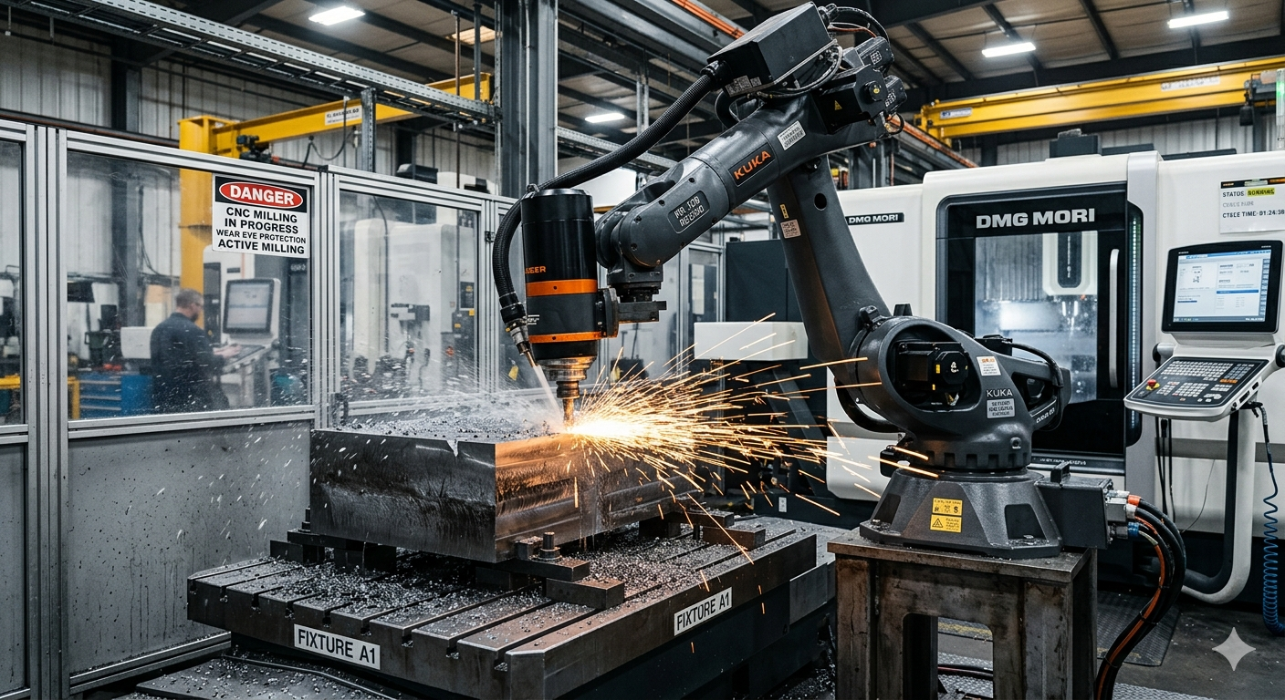

Why Robotic Milling Vibration Problems Are Often Misdiagnosed
The problem in robotic milling is rarely the spindle alone. In many installations, vibration appears after commissioning because the robot, spindle package, tooling strategy, and CAM programming were evaluated separately instead of as one dynamic system. The result is a cell that can technically remove material but struggles with chatter, unstable surface finish, inconsistent tolerances, or excessive tool wear.
Robotic milling vibration becomes difficult because industrial robots were not originally designed as machine tools. Their flexibility creates advantages in reach and accessibility, but it also introduces structural compliance that reacts differently than a rigid CNC machine. A spindle that behaves acceptably on one robot may become unstable on another due to mounting position, arm extension, payload distribution, or trajectory strategy.
The production risk is that the plant interprets vibration as a tooling issue and starts changing cutters, feeds, or spindle speeds without addressing the larger integration problem. In practice, vibration control depends on how the robot structure, spindle characteristics, workpiece rigidity, and CAM path interact during cutting.
Before investing in robotic milling, manufacturers should evaluate whether the process actually benefits from robotic flexibility or whether the operation requires the structural rigidity of a CNC machine. URT already explores this comparison in its article. Advanced CNC Machining and Automation Technologies Increase Production and Savings
Why Robot Structure Has a Direct Impact on Milling Stability
In robotic milling, the robot arm becomes part of the machining structure. This changes the vibration behavior completely compared to a fixed-frame CNC machine. Every axis position influences stiffness, resonance response, and cutting stability.
A robot may behave acceptably in one working envelope and become unstable in another. Long reach positions generally reduce rigidity because the arm extension increases leverage and deflection under cutting loads. Wrist orientation also matters. Certain axis configurations amplify compliance near the spindle interface, especially during side milling or aggressive material removal.
The practical consequence is that robotic milling cannot be evaluated only by payload or reach. Two robots with similar nominal capacity may behave very differently during cutting because their structural rigidity, gear train characteristics, and arm geometry respond differently to dynamic loads.
Toolpath Position Changes Structural Behavior
Many robotic milling problems appear only after production starts because the process was validated in one robot position while actual machining occurs across a wider envelope. As the robot moves, stiffness changes continuously.
Operations that maintain stable arm posture usually produce more predictable cutting behavior than operations requiring large posture transitions. Milling near the center of the robot’s stable workspace is generally easier to control than machining near maximum extension.
This is one reason why robotic milling cell layout matters as much as spindle selection. Fixture placement, robot base height, and part orientation directly influence vibration behavior because they determine how the robot carries cutting loads.
Spindle Selection Is About Dynamic Compatibility, Not Only Power
One of the most common mistakes in robotic milling projects is selecting the spindle primarily by RPM or power rating. A spindle that looks technically capable on paper may still create unstable cutting conditions if its mass, mounting method, or dynamic response do not match the robot.
Heavier spindles increase inertia at the wrist. This can reduce robot responsiveness and amplify vibration during acceleration or directional changes. High-speed spindles also introduce their own dynamic frequencies, which may interact negatively with robot structural resonances.
The spindle mounting interface matters as well. Weak mounting structures or poorly reinforced adapter plates often become vibration amplification points. In some robotic milling cells, the spindle bracket creates more instability than the spindle itself.
Cutting Strategy Changes Spindle Behavior
The spindle behaves differently depending on the cutting process. Light trimming operations may remain stable with relatively flexible robot configurations, while aggressive material removal introduces cutting forces that exceed the robot’s dynamic stability range.
Materials also matter. Composite trimming, foam machining, aluminum milling, and steel cutting create completely different vibration environments. A robotic milling system optimized for composite processing may become unstable in harder metals because the cutting forces rise dramatically.
For this reason, robotic milling vibration cells should be validated against the actual production material, cutter geometry, and expected removal rates rather than theoretical spindle capability alone.
CAM Strategy Often Determines Whether the Process Becomes Stable
CAM programming has a direct influence on robotic milling vibration because the toolpath controls how cutting forces enter the robot structure. Two programs cutting the same geometry can produce completely different stability outcomes.
Sharp directional changes, abrupt entry moves, inconsistent stepovers, and unstable acceleration profiles can introduce force spikes that excite robot vibration modes. In many robotic milling cells, improving the CAM strategy reduces vibration more effectively than changing hardware.
This is particularly important because industrial robots do not respond to cutting loads the same way CNC machines do. The robot controller must continuously compensate for axis movement while handling dynamic machining forces.
Toolpath Consistency Reduces Dynamic Shock
Smoother cutting engagement generally produces more stable robotic milling vibration conditions. Continuous tool engagement strategies reduce sudden load variation that can destabilize the robot arm.
Trochoidal milling, adaptive clearing, and gradual engagement paths can help reduce vibration because they avoid aggressive force peaks. However, these strategies only work when the robot controller, spindle response, and process stability support them.
Programming efficiency also affects commissioning time. Plants evaluating robotic machining often underestimate how much optimization is required between offline programming and stable production behavior. URT discusses related integration challenges in its article about. Robotic Machining and Milling
Feed Rate Optimization Is Not Linear
Reducing the feed rate does not automatically eliminate vibration. In some robotic milling vibration processes, slower cutting actually increases chatter because the cutter remains engaged longer within an unstable frequency range.
The relationship between spindle speed, feed rate, radial engagement, and robot stiffness is highly interactive. Stable cutting windows may exist only within narrow parameter ranges.
This is why robotic milling process development often requires iterative testing rather than direct transfer of CNC machining parameters.
For broader industrial robotics safety context, OSHA’s robotics guidance explains how robotic systems should be evaluated as integrated manufacturing environments.
Fixture Stability Is Frequently the Hidden Vibration Source
Plants often focus heavily on the robot and spindle while underestimating workpiece fixturing. In robotic milling, unstable fixtures can amplify vibration throughout the entire process.
Large parts, thin-wall components, or unsupported structures may resonate under cutting loads. Even when the robot itself is relatively stable, fixture movement can create chatter patterns that appear to originate from the spindle.
Fixture rigidity becomes especially critical in aerospace, composite, and trimming applications where part geometry changes stiffness across the machining path.
Part Presentation Affects Cutting Consistency
Inconsistent workpiece positioning creates another source of instability. If the robot encounters variable cutting engagement because the part location shifts between cycles, vibration behavior also changes.
This creates a common production problem: a robotic milling cell that performs well during initial validation but becomes inconsistent during real production variation.
Process repeatability depends on the entire cell architecture — robot, spindle, fixture, tooling, and material condition — rather than the robot alone.
When Robotic Milling May Not Be the Right Choice
robotic milling vibration is attractive because of its flexibility, workspace size, and lower capital cost compared to some large CNC systems. However, there are situations where robotic machining introduces more operational risk than benefit.
Processes requiring extremely tight tolerances, heavy metal removal, or highly rigid cutting conditions may exceed the practical stiffness limits of industrial robots. In those cases, vibration mitigation may become so restrictive that the productivity advantage disappears.
Very high-precision finishing operations can also become difficult when the robot structure cannot maintain stable dynamic behavior across the full machining envelope.
Some plants attempt robotic milling before stabilizing upstream production variables such as part consistency, fixture repeatability, or process sequencing. This usually shifts instability into the machining cell rather than solving it.
Manufacturers evaluating robotic machining should also compare integration complexity, maintenance requirements, and long-term process tuning against conventional machining alternatives.
Integration Checks Before Commissioning a Robotic Milling Cell
Before approving a robotic milling project, manufacturers should evaluate the full dynamic system rather than individual components in isolation.
The following checks help identify common vibration risks before commissioning:
- Robot posture stability across the full machining envelope
- Spindle mass compatibility with wrist dynamics
- Fixture rigidity under expected cutting loads
- Toolpath smoothness and engagement consistency
- Controller communication latency and motion synchronization
- Cutting force stability across material variations
- Thermal behavior during long production cycles
- Tool holder balance and spindle mounting rigidity
- Accessibility for maintenance and spindle replacement
- Process validation using actual production materials
Plants evaluating broader automation readiness may also benefit from reviewing How Robotic Machining Helps to Make Your Life Simple? especially when robotic machining is part of a larger automation roadmap.
Process Monitoring Matters More in Robotic Milling Than Many Plants Expect
Robotic milling cells often require ongoing monitoring because vibration behavior changes over time. Tool wear, spindle bearing condition, fixture degradation, and robot backlash can gradually shift the process outside stable cutting conditions.
Unlike some conventional machining environments where rigidity masks smaller process changes, robotic milling systems tend to expose instability earlier because the structure is more dynamically sensitive.
Monitoring spindle load, vibration trends, tool life consistency, and surface finish variation can help identify problems before they become severe enough to stop production.
How Robotic Milling Vibration Affects Surface Finish
Robotic milling vibration becomes more visible during long tool engagement paths where cutting forces remain unstable. Surface finish problems often appear before major dimensional errors, which is why vibration monitoring is important during robotic machining validation.
FAQ
Why does robotic milling create more vibration than CNC machining?
Industrial robots generally have lower structural rigidity than CNC machine frames. The robot arm, wrist, gearbox system, spindle mounting, and changing arm posture all influence vibration behavior during cutting.
Can spindle upgrades solve robotic milling chatter problems?
Not always. A higher-power or higher-speed spindle may still produce unstable cutting conditions if the robot structure, fixture rigidity, or CAM strategy remains unsuitable for the process.
Does slower cutting always reduce robotic milling vibration?
No. In some cases, reducing the feed rate or spindle speed can move the process into an unstable frequency range and increase chatter instead of reducing it.
Why does the robot’s position affect milling stability?
Robot stiffness changes throughout the working envelope. Extended arm positions and certain wrist orientations generally reduce rigidity and increase sensitivity to cutting forces.
What materials are most suitable for robotic milling?
Applications involving lighter cutting forces, such as composite trimming, plastics, foam, or some aluminum operations, are often easier to stabilize than heavy steel machining processes.
Should robotic milling parameters be copied directly from CNC programs?
Usually not. Industrial robots respond differently to dynamic cutting loads, so spindle speed, feed rate, engagement strategy, and acceleration profiles often require separate optimization.
Can robotic milling vibration reduce tool life?
Yes. Robotic milling vibration can accelerate uneven tool wear because unstable cutting loads create repeated force variation at the cutting edge. This often reduces predictability in tool life management.
Talk to RHS About Robotic Milling Integration
Robotic-HiTech Solutions does not simply sell technology: it drives a new way of understanding manufacturing, where industrial precision meets creativity.
Its work reflects the future of automation: robots capable of producing, sculpting, building, and expanding the limits of what is possible.