English
 Italiano
 Українська
 Русский
 Español

The 3D-printed train station in Japan at Hatsushima demonstrates how off-site additive manufacturing and rapid modular assembly can reduce the amount of structural construction performed beside an active railway. The small station building in Arida, Wakayama Prefecture, was created from four 3D-printed components manufactured away from the railway, reinforced with steel and concrete, transported by truck, and installed by crane during an overnight possession.
The widely repeated claim that the complete station was “printed and built in six hours” is incomplete. Printing the components required seven days, while the structural assembly on site took approximately two hours. Additional fixing, inspection, external works, interior construction, and installation of passenger equipment continued afterward.
The project is significant because it connected robotic material deposition with structural engineering, prefabrication, railway logistics, local architectural identity, and a tightly controlled installation window. It was not simply a construction printer operating beside the tracks.
Quick Answer
- Location: Hatsushima Station on JR West’s Kisei Main Line in Arida, Wakayama Prefecture.
- Building type: a 9.9 m² single-storey reinforced-concrete station waiting room.
- Production: four components were printed off site using a robot-mounted extrusion nozzle.
- Material system: special mortar shells were reinforced internally with steel and concrete.
- Manufacturing time: the printed parts were produced over seven days.
- On-site assembly: the main assembly sequence took approximately two hours.
- Service date: the new station building opened to passengers on 22 July 2025.
The project demonstrates rapid assembly of prefabricated 3D-printed components, rather than the complete construction of a finished railway station in one night.
What Was Built at Hatsushima Station?
The project replaced an ageing wooden station building at Hatsushima Station, an unstaffed stop on JR West’s Kisei Main Line.
The new structure is a compact passenger waiting facility with:
- a floor area of 9.9 square metres;
- a height of approximately 2.6 metres;
- a width of approximately 6.3 metres;
- a depth of approximately 2.1 metres;
- reinforced-concrete construction;
- a two-person bench;
- a ticket machine;
- a simplified IC-card reader.
The walls incorporate relief designs inspired by mandarin oranges and beltfish, products associated with Arida. The layered surface created by the additive process was used as part of the architectural expression rather than hidden completely.
The building is therefore both a functional railway facility and a pilot project for evaluating whether construction 3D printing can support the renewal of small railway buildings.
Was It Really the World’s First 3D-Printed Train Station?
JR West, JR West Innovations, and Serendix presented Hatsushima as the first railway station building constructed using construction 3D-printing technology.
The wording requires some precision.
The project does not mean that:
- an entire railway station complex was printed;
- the railway platform and track infrastructure were printed;
- the finished building emerged directly from one printer on site;
- all components were created exclusively through additive manufacturing;
- no conventional reinforcement, concrete, transport, lifting, or finishing was required.
The innovation lies in using 3D-printed permanent form components as part of a reinforced-concrete railway building and completing its structural installation within the limited overnight railway work window.
Editorial distinction: “world’s first” is the classification used by the companies responsible for the project. It should be attributed to them rather than presented as an independently audited universal classification.
Why the Six-Hour Claim Is Misleading
The initial project target was to complete the structural work, including the foundation-related assembly operations, between the departure of the last train and the arrival of the first train—an available window of approximately six hours.
That does not mean the complete project required only six hours.
| Project Stage | Reported Duration or Timing | What Happened |
|---|---|---|
| Design and Engineering | Completed before fabrication | Architectural design, structural design, segmentation, reinforcement, lifting, and installation were planned. |
| Off-Site Printing | Seven days | Four special-mortar components were printed in Minamata, Kumamoto Prefecture. |
| Reinforcement and Preparation | Before transport | Steel reinforcement and concrete were added inside the printed parts. |
| Transport | Before the installation night | The four components were delivered to Hatsushima on four trucks. |
| Main Assembly | Approximately two hours | A crane lifted the components from the trucks and positioned them on site. |
| Net Lifting and Placement | Approximately 1 hour 15 minutes | Around 45 minutes of the two-hour sequence involved exchanging trucks. |
| Overnight Completion | Finished by approximately 05:00 | Transport fittings were removed, components were secured, and planned overnight work was completed. |
| Interior and External Works | Following months | Finishes, exterior work, electrical equipment, ticketing, and passenger facilities were completed. |
| Passenger Opening | 22 July 2025 | The completed waiting-room building entered service. |
The overnight achievement remains technically relevant. The correction is that it describes rapid structural assembly—not the complete design, printing, reinforcement, transport, fit-out, and commissioning process.
How the Station Components Were 3D Printed
The building components were manufactured at a partner facility in Minamata, Kumamoto Prefecture.
A construction 3D-printing system used a nozzle mounted on a robotic arm to deposit a dedicated mortar material layer by layer.
The printing process created the external geometry of:
- the walls;
- the roof-related structural form;
- the foundation-related components;
- the decorative wall reliefs;
- the interfaces required for transport and assembly.
The printed material did not function alone as the final structural system. After printing, the parts received internal reinforcement and concrete filling to create reinforced-concrete components.
This distinction matters because the printer produced geometrically controlled shells and forms. Conventional structural materials and engineering provided the strength required by the completed building.
Was the Concrete Itself Printed?
The system extruded a special mortar through the printing nozzle. The printed sections then received steel reinforcement and poured concrete internally.
The process can be understood as a hybrid between:
- construction-scale additive manufacturing;
- stay-in-place formwork;
- reinforced-concrete construction;
- off-site prefabrication;
- modular site assembly.
Describing the building simply as “3D-printed concrete” hides this layered construction method.
The printed mortar provides:
- the external geometry;
- the visible layered texture;
- complex decorative features;
- the form into which structural material is introduced.
The reinforcement and concrete filling provide structural continuity and strength.
Why the Components Were Printed Off Site
Printing away from the railway created a more controlled manufacturing environment.
Off-site production allowed the team to manage:
- printer installation and calibration;
- material storage and preparation;
- temperature and production conditions;
- continuous access to the components;
- reinforcement and concrete filling;
- inspection before transport;
- work without interfering with train operations.
Printing directly beside an operational railway would have introduced additional constraints:
- restricted working hours;
- railway electrical and safety rules;
- limited equipment space;
- passenger and train separation;
- weather exposure;
- material-delivery logistics;
- greater risk if a print failed midway.
The project therefore used additive manufacturing as an off-site prefabrication method, then exploited modular construction to reduce the critical work beside the railway.
Why Four Components Were Used
The station was divided into four transportable sections.
Segmentation had to satisfy several competing requirements:
- each part had to fit the printer’s manufacturing envelope;
- components had to be transportable by road;
- their weight had to remain compatible with trucks and lifting equipment;
- the pieces needed suitable lifting points;
- the interfaces had to align on site;
- the assembly sequence had to fit the overnight access window;
- the completed joints had to satisfy structural requirements.
Printing one complete station shell would have reduced the number of joints but created major transport and lifting difficulties.
Producing many smaller parts could have simplified individual handling while increasing the number of connections, alignment operations, and installation time.
The four-part strategy was therefore an engineering decision connecting fabrication, logistics, railway access, and structural assembly.
How the Overnight Assembly Worked
Work began after the last train departed at 23:57 on 25 March 2025 and after railway procedures prevented trains from entering the work area.
The sequence included:
- confirming the railway possession and safe work area;
- bringing the first loaded truck into the station forecourt;
- connecting the crane to the printed component;
- lifting the part directly from the truck;
- positioning it at the building location;
- checking alignment;
- replacing the truck with the next loaded vehicle;
- repeating the sequence for all four components;
- removing transport attachments;
- securing and fixing the assembled structure;
- completing planned work before morning rail operations.
The assembly itself took approximately two hours. According to Serendix, about 45 minutes of that period involved changing the four trucks, leaving approximately 75 minutes of direct lifting and positioning work.
All planned overnight operations were completed by approximately 05:00.
Why Railway Construction Creates a Special Use Case
Construction beside active tracks is different from work on an unrestricted building site.
The project must account for:
- train movements;
- electrical infrastructure;
- restricted clearances;
- limited night-time work windows;
- formal track-possession procedures;
- passenger safety;
- rapid restoration of operational conditions;
- equipment and material access;
- the consequences of overrunning the approved schedule.
Conventional reinforced-concrete construction may require repeated night possessions for formwork, reinforcement, pouring, curing, stripping, and subsequent operations.
Prefabricating the major structure off site shifts much of that work away from the railway. The overnight operation becomes primarily a transport, lifting, alignment, and connection task.
The relevance of Hatsushima is therefore less about printing speed alone and more about reducing the duration of work performed inside a restricted railway environment.
How 3D Printing Supported the Architectural Design
Construction 3D printing can create curved surfaces, reliefs, and local geometric variation without manufacturing a unique conventional mold for every feature.
At Hatsushima, the walls included motifs inspired by:
- mandarin oranges;
- beltfish;
- the local identity of Arida;
- the visible layered character of the printing process.
The design demonstrates one of the clearer advantages of additive formwork: geometric and decorative information can be incorporated directly into the printing data.
With conventional precast construction, similar reliefs might require:
- custom form liners;
- additional mold fabrication;
- separate applied decorative elements;
- manual carving or finishing.
Additive manufacturing does not make design complexity free, but it changes where that complexity is managed. More of it can be encoded in the digital model and toolpath instead of in physical molds.
The Digital Workflow Behind the Station
A construction printer cannot interpret an architectural model directly without preparation.
The workflow likely includes several separate technical layers:
- Architectural Design: define dimensions, openings, passenger functions, appearance, and local motifs.
- Structural Design: determine reinforcement, concrete filling, joints, loads, and foundation behaviour.
- Component Segmentation: divide the building into printable and transportable modules.
- Print Preparation: adapt wall thicknesses, layer paths, openings, and reinforcement cavities.
- Toolpath Generation: convert geometry into ordered nozzle movements.
- Robot Simulation: verify reach, orientation, collisions, and path continuity.
- Material Parameters: coordinate deposition speed, mortar flow, bead dimensions, and layer timing.
- Quality Inspection: check printed geometry before reinforcement and transport.
- Lifting Engineering: define temporary lifting points, transport supports, and installation sequence.
- Site Registration: align the digital component positions with the real foundation and railway environment.
The printing robot executes only one stage inside this larger process.
Why Robot Movement and Mortar Flow Must Be Coordinated
Construction extrusion depends on the relationship between nozzle movement and material delivery.
The deposited bead is influenced by:
- robot speed;
- mortar-flow rate;
- nozzle shape and dimensions;
- layer height;
- material viscosity;
- acceleration and deceleration;
- corner geometry;
- time between layers;
- temperature and environmental conditions.
If the nozzle moves too rapidly, the bead may become thin, discontinuous, or poorly bonded. If it moves too slowly, material may accumulate and distort the geometry.
The printer must also manage starts, stops, openings, decorative forms, and transitions between walls.
Accurate robot motion cannot compensate for an unstable mortar-delivery process.
What “Millimetre Precision” Would Actually Require
Broad claims about millimetre-level precision should be treated carefully unless a specific measured tolerance is published for the completed building.
Final dimensional performance depends on:
- robot calibration;
- nozzle calibration;
- material-bead variation;
- layer deformation;
- concrete filling;
- reinforcement position;
- curing and shrinkage;
- transport movement;
- lifting deformation;
- foundation and component alignment;
- joint tolerances.
The robot may repeat a programmed path precisely while the wet material produces a different physical edge or wall thickness.
Construction accuracy must therefore be measured on the manufactured and assembled components rather than inferred from the robot specification alone.
Why Printing Time Is Only One Production Metric
The seven-day printing period does not describe the complete manufacturing duration.
Additional operations may include:
- material preparation;
- printer setup;
- component curing;
- reinforcement installation;
- concrete filling;
- quality inspection;
- surface repair;
- installation of lifting hardware;
- transport preparation;
- loading and delivery.
A fair comparison with conventional construction should compare equivalent scopes:
- design to completed structure;
- factory production time;
- critical on-site time;
- total labour;
- total cost;
- maintenance requirements;
- service life;
- future replacement or repair.
The strongest demonstrated advantage at Hatsushima was the short structural installation window beside an operational railway.
Does the Project Prove Lower Construction Costs?
JR West and Serendix stated that the project would be used to evaluate construction and maintenance cost effects.
This means cost reduction was an objective to be assessed, not a universal result already proven for every station.
Total project cost can include:
- architectural and structural engineering;
- digital modelling;
- printing equipment;
- special mortar;
- reinforcement and concrete;
- factory labour;
- quality control;
- four trucks;
- crane mobilisation;
- railway possession and safety procedures;
- interior work;
- passenger equipment;
- maintenance and inspection.
The technology may become economical when:
- several similar buildings share one design system;
- restricted site access makes conventional work expensive;
- formwork complexity is high;
- overnight possession time has substantial operational value;
- digital components can be reused across multiple station projects.
A single pilot cannot establish the economics of an entire railway renewal programme.
Does 3D Printing Automatically Reduce Material Waste?
Additive manufacturing can remove the need for some conventional formwork and deposit material according to a digital geometry.
Potential efficiencies may include:
- less disposable custom formwork;
- digitally controlled quantities;
- integrated decorative geometry;
- reduced rework through prefabrication;
- fewer site-cut materials;
- repeatable production of related components.
The complete environmental assessment must still include:
- special mortar production;
- steel reinforcement;
- concrete filling;
- printing energy;
- failed or test prints;
- transport from Kumamoto to Wakayama;
- four trucks and crane operations;
- future maintenance;
- service life and end-of-life processing.
Fewer molds do not automatically establish lower lifecycle impact. Sustainability requires measured comparison with a realistic conventional alternative.
How the Project Responds to Labour Constraints
JR West identified labour shortages and the need for planned renewal of railway facilities as reasons for investigating the technology.
Construction 3D printing may change labour requirements by shifting work toward:
- digital modelling;
- printer operation;
- material control;
- robot programming;
- quality inspection;
- off-site reinforcement;
- transport planning;
- crane installation;
- modular connection work.
It does not eliminate workers.
The process still requires:
- architects;
- structural engineers;
- robot and printer specialists;
- material technicians;
- reinforcement and concrete workers;
- truck drivers;
- crane operators;
- railway safety personnel;
- electricians and interior contractors;
- inspectors and maintenance teams.
The practical benefit is a redistribution and possible reduction of repetitive or prolonged work beside active tracks.
Could the Method Be Used at Other Railway Stations?
JR West stated that Hatsushima would serve as a base model for considering expansion to other stations and railway facilities.
Transfer to another site would require evaluation of:
- station dimensions;
- passenger volume;
- required rooms and facilities;
- platform and track clearances;
- road access for large trucks;
- crane positioning;
- available overnight possession;
- foundation conditions;
- local climate and exposure;
- seismic and structural requirements;
- utility connections;
- local design and planning requirements.
The Hatsushima model is most immediately relevant to small station buildings with limited internal functions.
A larger staffed station containing offices, toilets, retail, technical rooms, vertical circulation, or complex passenger circulation would require a significantly different system.
Could the Station Have Been Built With Conventional Prefabrication?
Rapid overnight assembly is not exclusive to 3D printing. Conventional precast concrete, steel framing, timber modules, or volumetric prefabrication can also reduce on-site work.
The relevant comparison is therefore not between 3D printing and fully manual construction alone.
| Construction Method | Potential Strength | Key Question |
|---|---|---|
| 3D-Printed Permanent Formwork | Geometric freedom, integrated reliefs, reduced custom molding, digital variation. | Do these benefits justify specialised printing and material systems? |
| Conventional Precast Concrete | Established structural standards, factory quality, rapid assembly. | Would reusable molds be more economical for repeated identical buildings? |
| Steel Framing | Lightweight components, established fabrication, fast erection. | What corrosion, fire, enclosure, and maintenance requirements apply? |
| Timber or Engineered-Wood Modules | Lightweight transport, prefabrication, renewable material options. | How will durability, moisture, fire, and maintenance be managed? |
| Volumetric Prefabrication | High level of off-site completion and very rapid installation. | Can the complete module be transported and lifted into the site? |
The case for 3D printing is strongest when its geometric flexibility, mold-free production, digital customisation, or component integration creates value beyond ordinary prefabrication.
What Are the Main Technical Limitations?
- The building was not printed completely on site. Production required an off-site factory, transport, and crane assembly.
- Printing was only one stage. Reinforcement, concrete filling, fixing, finishing, and equipment installation remained necessary.
- The project is small. Results from a 9.9 m² waiting room cannot be transferred directly to major station buildings.
- Material behaviour affects accuracy. Mortar deposition, curing, reinforcement, and concrete filling influence final geometry.
- Transport limits component size. Parts must fit road, truck, weight, and lifting constraints.
- Joints require engineering. Modular components must align and transfer loads correctly.
- Cost advantages remain project-specific. Equipment, logistics, and engineering must be included in the comparison.
- Lifecycle performance still needs observation. Maintenance, weathering, repair, and durability should be evaluated over time.
- Rapid assembly does not equal rapid project delivery. Design, production, interiors, systems, and approvals remain outside the overnight window.
- Other prefabrication methods may also be viable. 3D printing must be compared against realistic alternatives.
Can Industrial Robots Be Used for Similar Infrastructure Components?
Industrial robots can serve as movement platforms for construction printing when their reach, payload, controller, environmental protection, and software workflow suit the application.
Potential infrastructure applications include:
- small service buildings;
- railway waiting shelters;
- utility enclosures;
- architectural panels;
- formwork;
- street furniture;
- retaining or landscape elements;
- custom precast shells;
- replacement components for remote facilities.
The robot is only one component. The complete system requires:
- a construction extrusion head;
- a pump and material-delivery system;
- print-path software;
- robot simulation;
- material qualification;
- quality control;
- reinforcement strategy;
- structural engineering;
- safe operating infrastructure.
A handling or welding robot cannot become a construction printer through a nozzle change alone.
Could a Refurbished Robot Support Construction 3D Printing?
A refurbished industrial robot could potentially support construction-scale material deposition when its technical characteristics match the system.
The evaluation should verify:
- required reach and usable printing envelope;
- extruder and hose payload;
- controller generation;
- offline-programming compatibility;
- program and data capacity;
- communication with pumps and process controls;
- mechanical condition and backlash;
- robot calibration;
- environmental protection;
- availability of system backups;
- spare parts and technical support.
Construction printing may involve long continuous paths, abrasive materials, changing loads, dust, moisture, and demanding environmental conditions.
The robot must be assessed as part of the full printing cell rather than selected solely because it is available at a lower acquisition cost.
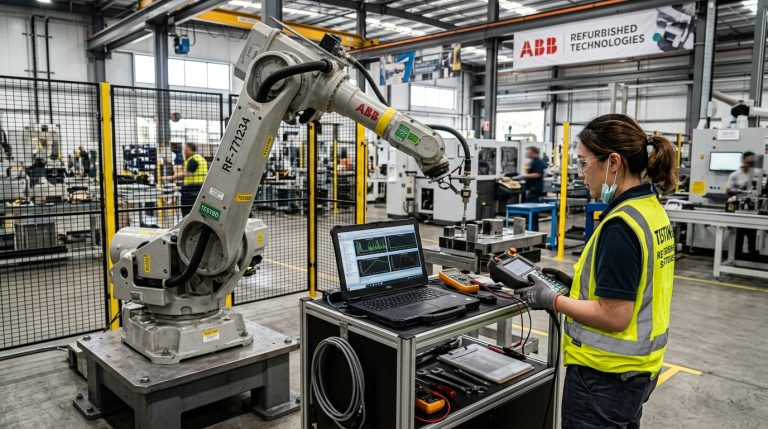
RHTS provides new and refurbished industrial robots that can be evaluated for additive manufacturing, construction research, large-scale extrusion, and digital fabrication.
How to Evaluate a 3D-Printed Infrastructure Project
Construction 3D Printing Evaluation Framework
- Infrastructure Function: What building or component must be produced?
- Scale: What dimensions, loads, internal functions, and service conditions apply?
- Printing Strategy: Will components be printed on site or manufactured off site?
- Material System: What mortar, concrete, reinforcement, and curing method are required?
- Robot or Printer: What working envelope, controller, nozzle, and material-delivery equipment are necessary?
- Segmentation: How will the design be divided for printing, transport, lifting, and assembly?
- Logistics: Can trucks, cranes, materials, and workers access the site?
- Installation Window: What operational restrictions limit on-site work?
- Structural Validation: How will reinforcement, joints, loads, fire, weather, and seismic conditions be addressed?
- Quality Control: Which dimensions, material properties, and assembly tolerances must be measured?
- Economics: Does the comparison include design, factory production, transport, installation, finishing, and maintenance?
- Lifecycle: How will the structure be inspected, repaired, and eventually replaced or dismantled?
If the structural system, transport strategy, installation window, and lifecycle requirements are undefined, selecting the printer or robot is premature.
Frequently Asked Questions
Where Is the 3D-Printed Train Station in Japan?
The building is at Hatsushima Station in Arida, Wakayama Prefecture, on JR West’s Kisei Main Line.
Was the Entire Station Built in Six Hours?
No. The four printed structural components were manufactured off site over seven days. Their main on-site assembly took approximately two hours, and all scheduled overnight structural operations were completed before the first morning train. Interior and external works continued afterward.
Was the Station Printed Directly Beside the Railway?
No. The components were printed at a partner factory in Minamata, Kumamoto Prefecture, reinforced, filled with concrete, transported by truck, and installed by crane at Hatsushima.
How Many Parts Were Used?
The station’s principal printed structure was divided into four components that could be transported separately and assembled on site.
What Material Was Printed?
A dedicated special mortar was extruded through a robot-mounted nozzle. The printed components were subsequently reinforced internally with steel and concrete.
How Large Is Hatsushima Station’s New Building?
The single-storey reinforced-concrete waiting room has an area of 9.9 m² and measures approximately 6.3 metres wide, 2.1 metres deep, and 2.6 metres high.
When Did the New Station Open?
The completed waiting-room building entered passenger service on 22 July 2025.
Why Was 3D Printing Used?
The project investigated whether off-site additive manufacturing could reduce work beside active tracks, shorten structural installation, avoid some conventional formwork, and support digitally customised station designs.
Did 3D Printing Eliminate Conventional Construction?
No. The project still required structural engineering, steel reinforcement, concrete, trucks, crane lifting, connections, interior works, electrical systems, passenger equipment, inspection, and conventional site labour.
Can the Same Method Be Used for Larger Stations?
Potentially, but a larger station would introduce different structural, transport, passenger, utility, fire, regulatory, and assembly requirements. The Hatsushima project is most directly relevant to small railway buildings.
The Real Innovation Was Moving Construction Away From the Tracks
The 3D-printed train station in Japan is more accurately described as a digitally manufactured, reinforced-concrete, modular railway building assembled during a restricted overnight work window.
Its four primary components were not created instantly. They were designed, printed over seven days, reinforced, filled, inspected, transported, lifted, connected, finished, and equipped through a coordinated industrial process.
The approximately two-hour structural assembly remains an important result because railway construction is constrained by train schedules and strict safety procedures. Moving most production into an off-site factory reduced the amount of work that had to occur beside the operational line.
The project also demonstrates where construction 3D printing can create specific value: mold-free geometric variation, integrated local decoration, digital component production, and rapid modular installation.
It does not prove that every station should be printed or that additive manufacturing is automatically faster, cheaper, or more sustainable across the complete lifecycle.
That conclusion requires continued evaluation of cost, maintenance, durability, repeatability, and the performance of future projects.
Explore related analysis in the 3D Printing Robots section or read how FANUC and Leister robotic printing supports modular architectural fabrication.
Infrastructure owners, universities, construction-technology companies, and integrators can also contact RHTS with the intended material, component dimensions, required printing envelope, payload, controller, and digital workflow for an initial robotic-platform assessment.