English
 Italiano
 Українська
 Русский
 Español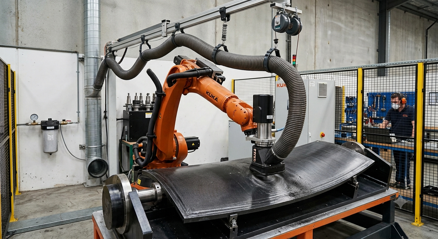

Composite robotic milling dust extraction must capture particles close to the cutting zone without disturbing robot movement, toolpath accuracy, workpiece stability, or measurement systems. Treating extraction as a separate housekeeping function often leads to poor capture, excessive airflow, blocked access, or hose forces that interfere with the programmed path.
Composite milling generates fine resin particles, fractured fibers, chips, and airborne dust. Their quantity and behavior depend on the composite material, cutter geometry, spindle speed, feed rate, tool orientation, and material-removal rate. The extraction system must therefore be designed around the actual machining process rather than the nominal spindle power.
Precision can be compromised when extraction equipment creates a variable mechanical load, unstable airflow, sensor contamination, or restrictions that force the robot into less rigid postures. The objective is controlled source capture with predictable airflow and mechanical behavior throughout the complete working envelope.
Define the Composite Dust Before Selecting Equipment
Identify the composite and resin system
Carbon-fiber-reinforced polymer, fiberglass, aramid composites, tooling board, and sandwich structures do not produce identical machining waste. Fiber conductivity, resin chemistry, particle size, and chip shape influence filtration, grounding, cleaning, and disposal requirements.
Review the material safety data sheet and the applicable occupational exposure, environmental, fire, and electrical requirements before specifying filters or separators. A system selected for fiberglass machining may not be suitable for conductive carbon-fiber dust or resin-rich particles.
Measure the real machining load
Estimate dust generation from the most demanding sustained production cycle, not from a short demonstration cut. Record tool diameter, flute count, spindle speed, feed rate, cutting depth, engagement, cycle duration, material-removal rate, and the number of robots that may operate simultaneously.
These values establish the airflow, collection capacity, filter area, and cleaning frequency that the system must support. Oversizing without process data can waste energy, while undersizing causes suction to decline as filters become loaded.
Composite dust extraction must capture fine particles close to the cutting tool without affecting robot movement, machining accuracy, surface finish, or measurement systems.
Composite Robotic Milling Dust Extraction at the Cutting Tool
Use a tool-mounted extraction hood
A compact hood or brush skirt around the spindle captures particles before robot motion and surrounding air currents disperse them across the cell. The hood should surround the emission zone without contacting the component, restricting tool access, or hiding the cutter during setup.
Replaceable or adjustable skirts are useful when different cutter lengths, tool diameters, and surface angles require different clearances. The design must also permit tool changes and routine inspection without extensive disassembly.
Maintain capture through changing tool orientations
A fixed hood that works during vertical routing may perform poorly when the robot mills horizontally, upside down, or inside a cavity. Capture performance must be validated at the least favorable tool orientations, including positions where gravity and cutter rotation direct particles away from the extraction opening.
Large components may require secondary perimeter extraction, partial enclosure, or a downdraft collection zone. These measures collect material that escapes the tool-mounted hood without relying entirely on high airflow at one extraction point.
Size Airflow by Capture Performance, Not Fan Power
Airflow must overcome particle momentum, cross-drafts, hood leakage, hose resistance, duct losses, and increasing filter pressure drop. A larger fan is not automatically better. Excessive suction can disturb lightweight laminates, affect vacuum fixtures, produce unnecessary noise, or create turbulence that carries fine dust away from the hood.
Effective composite robotic milling dust extraction depends on maintaining the required airflow at the hood after accounting for duct resistance, hose movement, filter loading, and simultaneous demand from other connected equipment.
The specification should define the required airflow at the capture hood under realistic loaded-filter conditions. Duct diameter, flexible-hose length, bends, reducers, branches, and separator losses must then be calculated so that adequate particle transport is maintained without excessive pressure loss.
Protect Robot Accuracy from Extraction Hose Forces
Separate hose support from robot movement
A heavy or poorly routed hose can apply changing forces to the spindle package as the robot moves. These forces may affect path accuracy, increase axis loading, or produce different levels of deflection according to robot posture and hose extension.
For this reason, composite robotic milling dust extraction must be treated as part of the robot’s mechanical configuration rather than as an accessory added after programming and calibration.
Use overhead supports, spring balancers, articulated carriers, controlled reels, or dedicated hose-management structures. The robot should carry as little unsupported and variable extraction load as practical.
Validate the complete working envelope
Simulate the extraction hose together with the robot, spindle, toolholder, cutter, fixture, component, safety fencing, and measurement equipment. Check minimum bend radius, torsion, compression, snagging, collision risk, and maximum hose extension at every programmed orientation.
This mechanical validation should be included in the wider cell-accuracy assessment. The interaction between the robot, foundation, support structure, fixture, and machining loads is examined further in why robot accuracy alone does not guarantee precision in robotic milling.
Choose Filtration and Collection for Composite Materials
Use staged particle separation
A pre-separator or cyclone can remove larger chips and heavy particles before they reach the main filter. This reduces filter loading, limits premature clogging, and helps maintain stable suction during long machining cycles.
Fine filtration should then be selected according to the measured particle distribution, exposure assessment, collector configuration, and local environmental requirements. Filter efficiency alone is insufficient if the collector cannot sustain the required airflow as resistance increases.
Control conductive and combustible dust risks
Carbon-fiber dust can be electrically conductive and may migrate into motors, connectors, controllers, sensors, and electrical cabinets. Conductive components should be grounded, and the cell layout should prevent contaminated air from passing through sensitive equipment.
Some resin-rich, plastic, or polymer dust mixtures may also require a combustible-dust assessment. Explosion protection, isolation, venting, suppression, antistatic hoses, or specialized collection equipment may be necessary depending on the material, dust concentration, collector location, and applicable regulations.
Prevent Extraction from Interfering with Metrology
Airborne dust can contaminate cameras, laser trackers, scanners, probes, calibration targets, and optical reference systems. Strong cross-flow may also move loose debris across measurement surfaces or disturb protective curtains. Extraction outlets should therefore be positioned so that contaminated air does not cross the measurement line of sight.
Where in-process measurement is required, coordinate extraction timing with probing or scanning cycles. A short settling period may be necessary after machining, but residual particles must remain contained when fan speed or damper position changes.
The final composite robotic milling dust extraction configuration should be tested with loaded filters, production toolpaths, different robot orientations, and the maximum expected material-removal rate.
Commission the system under production conditions.
Test more than visible cleanliness. A clean-looking cell does not prove that fine airborne particles are controlled. Commissioning should include airflow measurements, duct static-pressure readings, hood-capture visualization, filter differential pressure, and occupational exposure sampling performed by qualified personnel where required.
OSHA explains that local exhaust ventilation is intended to capture contaminants at or near their source rather than allowing them to disperse through the workplace. Its ventilation guidance provides a useful general reference when defining hoods, ducts, air-cleaning equipment, fans, and discharge arrangements.
The tests should represent new and partially loaded filters, different robot orientations, maximum material-removal rates, and simultaneous operation of all connected machines. This reveals whether capture performance declines during normal production rather than only under ideal startup conditions.
Composite robotic milling dust extraction must be commissioned under real production conditions. A clean-looking cell does not prove that fine airborne particles are controlled. Commissioning should include airflow measurements, duct static-pressure readings, hood-capture visualization, filter differential pressure, and occupational exposure sampling performed by qualified personnel where required.
Compare machining performance before and after extraction. Run equivalent parts using the final hood, hose routing, airflow settings, filter condition, and production toolpaths. Compare dimensional results, surface finish, robot following error, spindle load, vibration, and cycle time. Any significant change should be investigated before final process approval.
Use the following checklist to verify that the composite robotic milling dust extraction design supports particle control, robot movement, machining stability, and safe maintenance.
Practical Dust Extraction Design Checklist
- Define the composite, resin, particle behavior, and applicable hazards.
- Calculate dust generation from the highest sustained production rate.
- Capture particles at the cutter with the smallest practical hood opening.
- Validate suction during vertical, horizontal, inverted, and cavity machining.
- Support the extraction hose independently to reduce changing robot loads.
- Size ducts for both source capture and reliable particle transport.
- Monitor filter differential pressure and establish cleaning limits.
- Verify exposure control and machining accuracy during commissioning.
FAQ’s
Can one dust extractor serve several milling robots?
Yes, but the collector, duct network, and controls must be sized for simultaneous demand. Automatic dampers can isolate inactive branches, provided they do not reduce particle-transport velocity or create unstable airflow in the active branches.
Is a brush skirt always necessary around the spindle?
No. Brush skirts are effective for many routing and trimming operations, but deep cavities, complex angles, delicate surfaces, or long tools may require segmented skirts, side hoods, or combined local and enclosure extraction.
Can stronger suction improve dimensional accuracy?
Not directly. Adequate capture protects equipment and working conditions, but excessive airflow or hose force can introduce instability. Precision depends on balanced extraction, robot stiffness, tooling, fixturing, calibration, toolpaths, and cutting parameters.
How often should extraction filters be replaced?
Use differential-pressure limits, monitored airflow, material loading, and the filter manufacturer’s instructions rather than a fixed calendar alone. Replacement frequency varies with filter area, cleaning method, operating hours, and the type of composite being machined.
When should an extraction specialist join the project?
The specialist should participate during cell concept development. Early coordination allows the hood, ducting, hose support, collector, safety controls, and maintenance access to be integrated before the robot layout is frozen. For application-specific engineering support, contact Robotic Hi-Tech Solutions.
The extraction system should be validated against the actual composite material, production toolpaths, robot postures, filtration conditions, and regulations applicable to the installation. Airflow values and filter specifications should not be selected from generic recommendations alone.