English
 Italiano
 Українська
 Русский
 Español
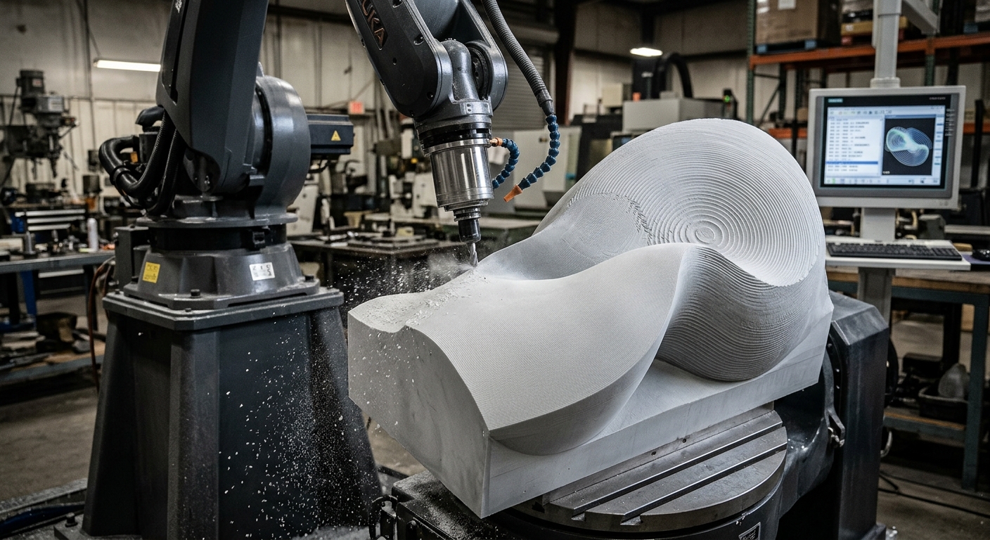

Robotic toolpath resolution changes how closely a manufactured sculpture follows its digital surface. It influences the visibility of machining marks, the reproduction of curved details, and the amount of finishing required. A high-resolution digital model cannot guarantee a smooth physical result if the robot follows a path that approximates the geometry too coarsely.
In robotic sculpture fabrication, resolution describes several related settings. These include the spacing between programmed positions, the distance between adjacent machining passes, and the permitted deviation between a calculated toolpath and the intended geometry. Each setting affects the finished surface differently, particularly when machining complex free-form shapes.
Choosing suitable resolution requires more than generating additional robot positions. Engineers must consider cutter geometry, material properties, controller behavior, robot stiffness, and the intended appearance of the artwork. This article explains how those factors interact, why excessive resolution may create programming difficulties, and how to evaluate surface quality before manufacturing a complete sculpture. The objective is to preserve meaningful geometric detail while maintaining stable, practical machining conditions.
What robotic toolpath resolution means in sculpture fabrication
Robotic toolpath resolution determines how precisely a programmed machining trajectory approximates the intended surface. It affects geometric accuracy, surface texture, and the number of instructions required to describe the machining operation. However, different resolution parameters control different aspects of the finished result.
Point spacing and geometric approximation
CAM software may approximate curved movements through a sequence of programmed positions. Greater distances between positions can produce visible geometric approximation errors, particularly around tight curves. Reducing that distance can improve the representation of curvature, provided the robot controller executes the trajectory as intended.
Stepover and visible machining marks
Stepover describes the lateral distance between adjacent tool passes. During finishing with a ball-end cutter, larger stepovers generally create more pronounced scallops between passes. Smaller stepovers reduce their theoretical height but increase the number of passes needed to cover the surface.
How geometric resolution influences curved sculpture surfaces
Digital sculptures frequently contain smooth transitions, changing curvature, and localized details. Robotic toolpath resolution determines how accurately these features are represented during machining. Poor geometric approximation can flatten subtle transitions or create visible faceting, particularly in areas where curvature changes rapidly.
Chordal tolerance and surface deviation
Chordal tolerance limits the permitted deviation between a curved toolpath and its geometric approximation. A smaller tolerance usually produces a closer approximation, although the result depends on the CAM method and controller interpretation. It does not independently determine machining accuracy.
Preserving local details
Areas containing sharp transitions or small decorative features may require finer path resolution than broad, gently curved surfaces. Adaptive programming can allocate more positions where curvature changes rapidly. The broader parametric robot workflow explains how digital geometry becomes executable robot instructions.
Why tool geometry changes the final surface
Even a geometrically accurate trajectory can produce an unsuitable surface when the cutting tool does not match the sculptural features. Robotic toolpath resolution must therefore be evaluated alongside tool diameter, shape, engagement, and orientation. Small recesses may remain inaccessible to a larger cutter regardless of programming resolution.
Ball-end cutters and surface scallops
Ball-end cutters are commonly considered for curved finishing operations because their rounded geometry can follow changing surface contours. However, adjacent passes leave residual material between their contact regions. The resulting scallop pattern depends on cutter geometry, stepover, and local surface orientation.
Tool orientation and contact conditions
Changing the tool angle changes its contact conditions and the direction of cutting forces. These changes can influence surface texture, vibration, and deflection. The relationship is examined in RHTS’s article on tool orientation and surface finish, particularly for multi-axis machining.
How robot motion affects programmed resolution
Robots do not necessarily reproduce every programmed point as a complete stop followed by another movement. Controllers may interpolate, blend, or smooth trajectories according to programmed settings and supported motion functions. Consequently, the executed trajectory can differ from the original geometric approximation.
Controller interpolation and trajectory smoothing
Very closely spaced positions can increase program size and place additional demands on motion planning. Depending on controller capabilities, the robot may slow down or modify its trajectory. Smoother motion can support better finishing, but excessive blending may reduce conformity to the intended geometry.
Acceleration and structural stiffness
Curved toolpaths can require continuous changes in joint velocities and acceleration. Robot configuration and structural stiffness influence the response to cutting forces. RHTS examines these effects in its guide to robot dynamics in robotic milling, including their relationship with surface quality.
When higher robotic toolpath resolution becomes counterproductive
Increasing robotic toolpath resolution is not automatically beneficial. Extremely dense trajectories may increase programming complexity without producing a measurable improvement in the finished sculpture. Once geometric approximation errors become smaller than other process deviations, further refinement may offer limited practical benefit.
Other factors can dominate the result. These include cutter deflection, workpiece movement, spindle runout, calibration errors, and material response. For example, reducing point spacing cannot eliminate surface waviness caused by unstable cutting conditions. Engineers should identify the dominant error before adjusting resolution.
How material properties influence surface reproduction
The same machining strategy can produce different surface textures in foam, wood, plastics, or composite materials. Robotic toolpath resolution influences geometric reproduction, but material stiffness, internal structure, and cutting behavior also affect visible tool marks. Some materials reveal regular machining patterns, while others develop defects associated with tearing or local deformation.
Material selection also affects finishing requirements. A sculpture intended for coating may tolerate machining marks that subsequent preparation removes. An exposed surface requires greater attention to the texture generated directly by the tool. Therefore, resolution settings should reflect the specified final appearance and subsequent operations.
How to evaluate toolpath resolution before production
Testing a representative section helps engineers evaluate robotic toolpath resolution before manufacturing a large sculpture. The sample should contain curved regions, surface transitions, and details similar to those in the final design. Comparing several settings under controlled conditions helps separate toolpath effects from other machining variables.
Practical checklist for surface quality validation
Use the following checks to establish a suitable machining strategy. Record settings and inspection results so the selected approach can be repeated or adjusted when the geometry changes.
- Inspect the digital geometry: Identify tight curves, small recesses, and regions where surface continuity affects appearance.
- Review chordal tolerance: Confirm that the generated path approximates important surface features within the project’s geometric requirements.
- Compare stepover values: Evaluate visible scallops and the corresponding changes in machining time.
- Check cutter accessibility: Identify features that cannot be machined with the selected tool diameter or orientation.
- Simulate robot motion: Examine reachability, joint configurations, trajectory transitions, and possible collisions.
- Machine representative samples: Compare surface results while keeping tooling, material, and relevant cutting conditions consistent.
- Inspect physical geometry: Measure specified features and examine surface texture under appropriate lighting conditions.
- Document accepted parameters: Record tool geometry, spacing, tolerances, motion settings, and necessary finishing operations.
How to balance sculpture detail, machining time and safety
The appropriate resolution depends on which details must survive fabrication and how the finished artwork will be evaluated. Broad surfaces may accept larger stepovers, while visible decorative regions require closer examination. Applying identical settings throughout a complex sculpture can increase machining time unnecessarily.
Engineers should compare surface requirements with cycle time, tool wear, and robot behavior. Any change to the machining program also requires appropriate verification of the operating conditions. OSHA provides guidance on industrial robot systems and safety, including risk assessment and safeguarding considerations.
Before approving production, document the accepted surface condition, machining parameters, inspection method, and finishing allowance. Organizations evaluating sculpture fabrication can contact Robotic Hi-Tech Solutions to discuss robot integration, tooling, programming, and manufacturing requirements for a specific project.
Frequently Asked Questions
What is robotic toolpath resolution?
It describes how precisely programmed tool movements approximate the intended geometry. Relevant parameters include point spacing, chordal tolerance, and the spacing between machining passes.
Does higher resolution always produce a smoother sculpture?
No. Smaller geometric deviations may improve surface reproduction, but vibration, cutter geometry, tool orientation, and material behavior can limit the final improvement.
What is the difference between point spacing and stepover?
Point spacing concerns positions along a trajectory. Stepover measures the lateral distance between adjacent machining passes. Both influence surface quality through different mechanisms.
Can a robot reproduce every detail in a digital sculpture?
Not necessarily. Cutter dimensions, accessibility, robot motion limits, and process accuracy can prevent certain features from being reproduced directly.
How does chordal tolerance affect curved surfaces?
It controls the permitted geometric deviation when approximating a curve. Smaller tolerances generally preserve curvature more closely but may increase path complexity.
Why can a highly detailed toolpath create motion problems?
Dense trajectories may challenge controller processing or motion planning. Depending on the system, they can introduce slowdowns or affect trajectory continuity.
How should surface quality be inspected?
Compare representative physical features against the CAD model. Use appropriate dimensional measurements and visual inspection to assess geometric deviations and machining marks.
When should toolpath resolution be adjusted?
Adjust it when inspection identifies geometric approximation errors, unacceptable scallops, or unnecessary machining time. Test changes before applying them to the complete sculpture.