English
 Italiano
 Українська
 Русский
 Español
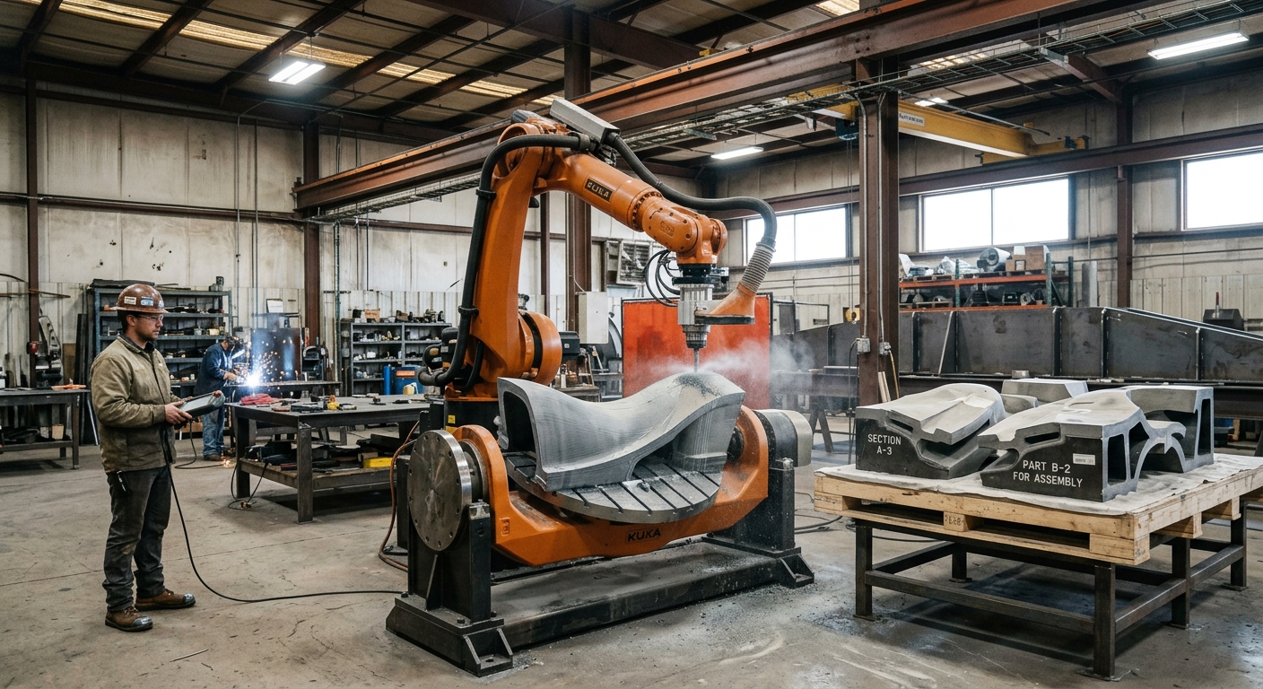

Dividing a large sculpture into smaller parts makes robotic fabrication possible when the complete artwork exceeds the robot’s working envelope, material stock dimensions, or available handling capacity. However, the division must preserve the intended shape while allowing each component to be manufactured, transported, and assembled accurately. Robotic sculpture fabrication therefore begins with decisions about geometry, structural connections, and production constraints rather than simply cutting a digital model into convenient pieces.
The main challenge is choosing where each separation should occur. Poorly positioned joints can interrupt visible surfaces, restrict cutting-tool access, weaken connections, or create alignment problems during installation. Moreover, a section that fits inside the robot’s reach may still be difficult to machine because of tool orientation, fixture interference, or insufficient clearance around the workpiece.
This guide explains how to divide complex sculptures using digital models, practical sectioning criteria, and assembly planning. It covers geometric analysis, material selection, robotic toolpaths, joining methods, dimensional inspection, and transportation. The objective is to create manageable components without compromising the design or introducing unnecessary manufacturing operations.
1. Understanding robotic sculpture fabrication constraints
Evaluating the complete sculpture geometry
Begin with a digital model representing the intended finished sculpture. Inspect its overall dimensions, surface curvature, internal cavities, overhangs, and areas requiring detailed finishing. These characteristics influence where sections can be separated and which manufacturing processes can access their surfaces.
The model should also identify structural interfaces, mounting points, and any internal support system. For example, a large outdoor installation may require a separate load-bearing framework. In that situation, segmentation must accommodate both the visible sculpture and its structural connections.
Understanding the robot’s working envelope
A robot’s nominal reach does not guarantee access to every surface. Tool length, wrist orientation, joint limits, fixtures, and collision zones reduce the usable manufacturing space. Therefore, evaluate each proposed section using the complete robotic cell configuration rather than robot reach alone.
2. Choosing where to divide the sculpture
Locating natural separation lines
In robotic sculpture fabrication, natural changes in shape often provide suitable locations for section boundaries. Curves, recesses, transitions, and concealed surfaces may accommodate joints without making them visually prominent. However, the final position must also permit reliable assembly and subsequent surface finishing.
For example, robotic sculpture fabrication involving several intersecting organic forms may require sections near their connection points. This approach can simplify individual manufacturing while preserving the intended appearance of the completed sculpture.
Balancing section size and complexity
Smaller sections can improve access and simplify handling, but excessive segmentation increases the number of joints and assembly operations. Larger sections reduce joint count yet may require more demanding fixturing or lifting arrangements. The appropriate division balances manufacturing access, material behavior, and installation requirements.
3. Designing joints and alignment features
Planning mechanical connections
In robotic sculpture fabrication, joint design depends on the material, structural requirements, and installation environment. Possible methods include mechanical fasteners, bonded connections, welded assemblies, and internal support structures. Each requires suitable preparation and verification before production.
Visible joints may be acceptable when they contribute to the artistic design. Otherwise, connection details should account for surface finishing and concealment. Avoid placing a joint where it would be inaccessible after neighboring components are installed.
Using alignment references
In robotic sculpture fabrication, alignment features help establish the relative position of adjoining sections. Depending on the material and process, these may include locating pins, machined reference surfaces, registration holes, or assembly fixtures. Their design must permit installation without forcing incompatible surfaces together.
Include assembly datums in the digital model. A datum is a reference feature used to establish position or orientation. Consistent references make it easier to inspect individual sections and identify alignment errors before final installation.
4. Preparing digital models for robotic manufacturing
Creating individual manufacturing files
In robotic sculpture fabrication, each component needs a separate manufacturing model after the separation boundaries are defined. These files should retain their relationship to the original sculpture coordinates. Identify mating surfaces, material allowances, mounting features, and surfaces requiring additional finishing.
Each section must also include appropriate manufacturing stock. For subtractive machining, enough material must remain for cutting and finishing. For additive fabrication, the model must account for deposition constraints and the intended orientation during production.
Checking model continuity
During robotic sculpture fabrication, compare adjoining digital sections before generating toolpaths. Check that mating geometry remains compatible and that no unintended gaps, overlaps, or missing surfaces were introduced during segmentation. Digital inspection cannot replace physical verification, but it can identify modeling problems before material is processed.
5. Planning robotic access and toolpaths
Evaluating machining accessibility
Robotic sculpture fabrication requires sufficient clearance for the cutting tool, spindle, robot wrist, and supporting equipment during milling. Deep cavities and complex overhangs may require workpiece repositioning or additional setups. In some cases, changing a section boundary can eliminate a difficult machining orientation.
For related manufacturing considerations, the RHTS article on AI-powered robotic stone carving discusses how digital models, machining software, and robotic equipment contribute to sculptural production.
Validating the manufacturing sequence
Simulate robot motion with the actual tool and cell geometry whenever suitable software is available. Check reachability, joint configurations, potential collisions, and workpiece access. The simulation should cover approach movements and repositioning operations, not only cutting or deposition paths.
6. Selecting fabrication methods and materials
Robotic milling and subtractive shaping
Robotic milling is one method used in robotic sculpture fabrication. It removes material from a larger block or prepared workpiece and can support production involving foam, wood, suitable plastics, and other machinable materials, provided the equipment and cutting process match the application.
Section boundaries should accommodate tool access, workholding, and subsequent joining. The RHTS article about large-scale robotic sculpture production at Kern Studios illustrates the use of separate manufactured components for large creative structures.
Robotic additive fabrication
Additive processes create components by depositing material according to programmed paths. Their suitability depends on the material system, deposition equipment, support requirements, and process stability. Some geometries may require a different orientation or subdivision to become manufacturable.
The article on robotic 3D printing for art and architecture provides further context about additive manufacturing with industrial robotic arms.
7. Preparing sections for transport and installation
Managing lifting and transportation
In robotic sculpture fabrication, manufacturing limits are only one consideration when defining section dimensions. Each completed component must also pass through available workshop openings, fit the transport arrangement, and remain manageable during unloading and positioning.
Determine the mass, center of gravity, lifting points, and support conditions for each section. Fragile extensions may require temporary protection or dedicated transport fixtures. The lifting arrangement must be assessed for the actual component geometry and handling equipment.
Considering operational safety
Fabrication and assembly planning should include hazards associated with robot motion, cutting equipment, lifting operations, and manual access. OSHA’s technical guidance on industrial robot system safety provides information about risk assessment and safeguarding for robotic applications.
8. Practical checklist for dividing and assembling sculpture sections
Before releasing manufacturing files for robotic sculpture fabrication, review the proposed section boundaries against the complete production and installation process. The following checks can help identify issues that are difficult to correct after fabrication begins.
- Confirm section dimensions: Compare each component with the usable robotic workspace, fixture dimensions, and available material stock.
- Inspect visible seams: Check how joint locations affect the final sculpture’s appearance and finishing requirements.
- Verify tool access: Evaluate cutting or deposition orientations, robot wrist clearance, and potential fixture collisions.
- Review joining methods: Define connection geometry, installation access, and the required structural verification.
- Establish alignment references: Include measurable datums or locating features for assembly and dimensional inspection.
- Check handling requirements: Assess section mass, lifting points, center of gravity, and transport protection.
- Define inspection criteria: Identify critical dimensions, mating surfaces, and acceptable deviations based on project requirements.
- Validate assembly order: Confirm that components can be positioned, connected, inspected, and finished in the intended sequence.
Before permanent joining, perform a trial assembly when practical. This allows the fabrication team to identify incompatible interfaces, inaccessible fasteners, and unexpected dimensional differences. Record corrections in the manufacturing documentation so the digital model matches the completed installation.
For projects involving complex geometry or multiple robotic processes, contact Robotic Hi-Tech Solutions to discuss robot configuration, manufacturing access, and equipment requirements for the proposed sculpture.
9. Frequently asked questions
How do you determine the number of sculpture sections?
The number depends on the artwork’s geometry, usable manufacturing space, material stock, connection design, and transportation restrictions. Evaluate several division strategies rather than choosing a fixed section count.
Can a robotic arm manufacture a sculpture larger than its reach?
Yes. A larger sculpture can be manufactured as separate components and assembled afterward. External axes or repositioning systems may also expand the usable manufacturing arrangement, depending on the robot configuration.
Where should joints be positioned on curved surfaces?
Prefer locations that allow reliable joining and finishing while minimizing unwanted visual interruptions. Recesses and geometric transitions may help, but structural requirements and tool access must also be considered.
Which materials are suitable for segmented robotic sculptures?
Materials may include foam, wood, plastics, stone, metals, and compatible additive-manufacturing compounds. Suitability depends on the selected process, equipment, joining method, and intended installation environment.
How can alignment errors between sections be reduced?
Use consistent coordinate references, measurable locating features, controlled fixtures, and dimensional inspection. A trial assembly can reveal differences before permanent connections or finishing operations are completed.
Should sections be joined before or after surface finishing?
That depends on the connection design and finishing process. Some surfaces are easier to finish individually, while concealed joints may require final blending after assembly. Plan both operations together.
Can robotic 3D printing produce separate sculpture modules?
Yes, provided the deposition process supports the selected material and component geometry. Module design must address printing orientation, dimensional variation, joining surfaces, and any required reinforcement.
What documentation is needed for final sculpture assembly?
Useful documentation includes component identification, assembly drawings, reference coordinates, joint details, lifting instructions, inspection records, and the intended installation sequence. Structural requirements should be reviewed by qualified personnel.