English
 Italiano
 Українська
 Русский
 Español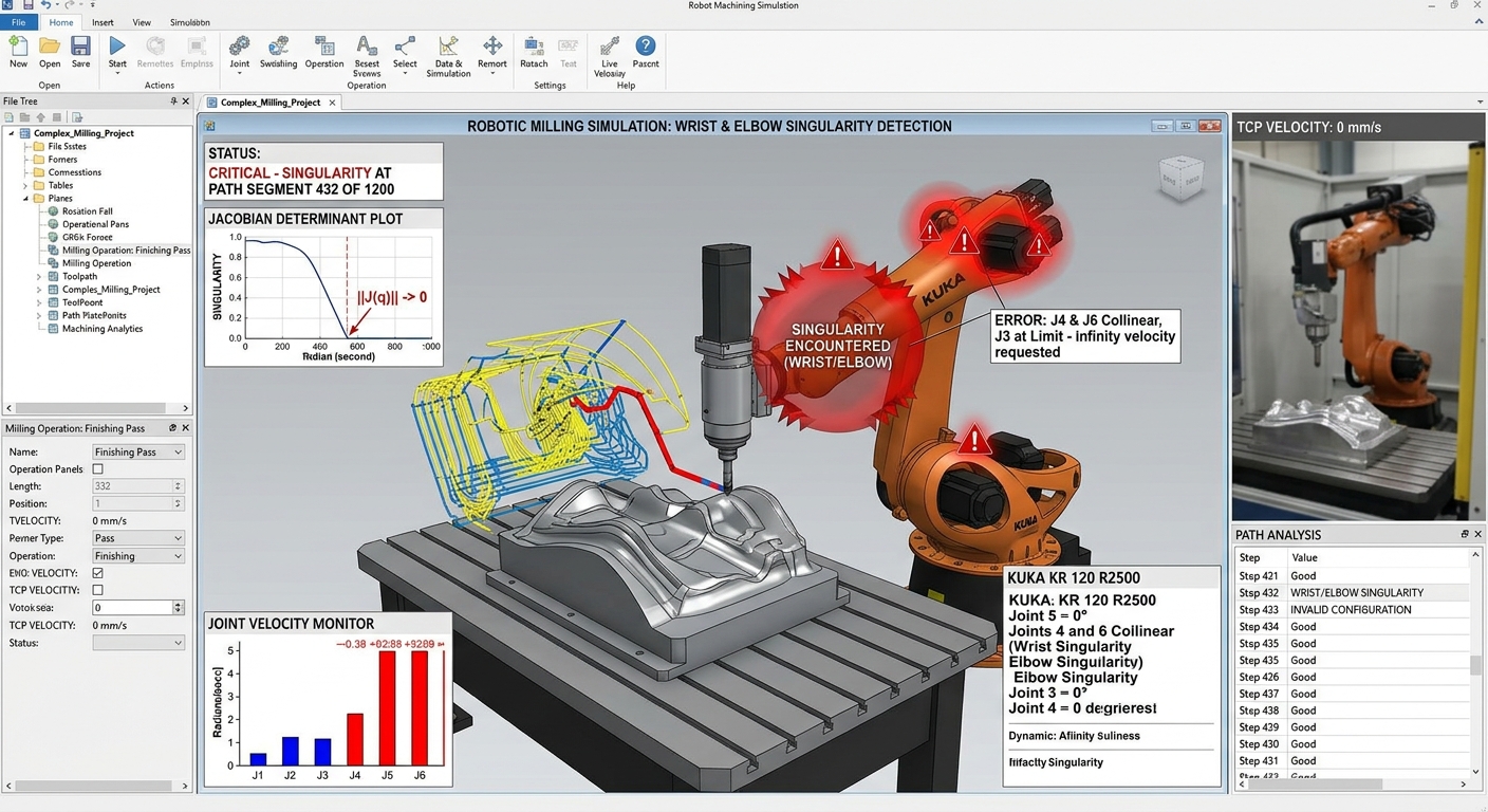

Robot milling singularities can turn a geometrically smooth machining path into difficult or unstable robot motion. The cutter may follow a continuous curve in the CAM system while one or more robot joints must rotate rapidly, change configuration, or approach their motion limits to maintain the commanded tool position and orientation.
This matters because milling depends on more than reaching each programmed point. The robot must maintain controlled tool orientation, predictable motion, suitable posture, and stable cutting conditions throughout the path. A singular or near-singular configuration can therefore create sudden joint-speed changes, unexpected wrist motion, controller slowdowns, or a path that cannot be executed as programmed.
The practical response is to evaluate robot kinematics together with the machining path before production. Simulation, joint-axis analysis, alternative tool orientations, workpiece placement, and path modifications can often move the robot away from problematic configurations. Singularities should be treated as a toolpath-planning constraint rather than as a problem discovered only after the milling program reaches the physical cell.
What Is a Robot Singularity?
A robot singularity is a configuration in which the relationship between Cartesian tool motion and individual joint motion becomes mathematically problematic. Around these configurations, a small requested movement or orientation change at the tool can require very large changes in one or more robot joints.
Why six-axis robots encounter singularities
A conventional six-axis articulated robot uses several rotary joints to position and orient its tool. Certain combinations of joint angles reduce the robot’s ability to produce independent motion in a particular Cartesian direction. The exact singular configurations depend on the robot’s kinematic structure.
A singularity is not the same as a joint limit
A joint limit occurs when an individual axis approaches the end of its permitted angular range. A singularity is a kinematic condition involving the relationship between multiple axes. The two problems are different, although a toolpath can encounter both at the same time.
How Robot Milling Singularities Affect Toolpaths
In robotic milling, the commanded path normally specifies both tool-center-point position and tool orientation. Maintaining that orientation across a curved surface can force the robot through configurations that are unfavorable from a kinematic perspective.
The Cartesian toolpath may still appear smooth. The joint-space trajectory, however, can contain rapid axis movement, configuration changes, or sharp velocity variations. This difference explains why reviewing only the cutter path in CAM is insufficient for robotic machining.
Joint speed can change rapidly
As the robot approaches certain singular configurations, a small change in tool orientation may require a much larger rotation of wrist axes. The controller must still respect its joint velocity and acceleration constraints, so the resulting motion may differ substantially from the apparently simple Cartesian command.
Tool orientation may become difficult to maintain
Complex surfaces often require continuous adjustment of the spindle direction. If that orientation strategy pushes the wrist toward a singular configuration, the robot may need an abrupt redistribution of motion between its axes. That behavior is undesirable during continuous cutting.
Why Singularities Matter More During Milling Than Simple Handling
A handling robot may occasionally tolerate a speed reduction or a modified transition if the part still reaches its destination correctly. Milling is more sensitive because the robot is interacting continuously with the material while following a programmed geometry. For this reason, robot milling singularities deserve specific attention during machining validation.
Changes in velocity, acceleration, wrist movement, and robot posture can alter cutting conditions. The practical consequence can be a visible toolpath transition, inconsistent engagement, vibration, or loss of process continuity. The severity depends on the robot, tool, material, cutting strategy, and location of the event.
Cutting forces continue during the motion problem
The cutter does not stop generating forces simply because the robot is approaching a difficult kinematic configuration. If robot motion becomes less stable while the tool remains engaged, structural compliance and process dynamics also become part of the problem.
Why CAM Geometry Alone Cannot Detect Every Problem
A CAM system can generate a valid machining path in Cartesian space without proving that a particular industrial robot can execute every target with a suitable joint configuration. Robotic machining therefore requires a kinematic layer between geometric toolpath generation and production execution, especially when robot milling singularities may appear along complex orientation changes.
That analysis should consider robot position, axis values, tool orientation, external axes when present, joint limits, collisions, and singular or near-singular regions. Robotic Hi-Tech Solutions also discusses the relationship between machining strategy, robot posture, CAM and execution constraints in its technical guides on robotic milling and automation.
Part placement changes the kinematic problem.
The same cutter path can produce very different robot configurations when the workpiece is moved or rotated within the cell. A path that passes close to a singularity in one setup may be easier to execute after changing the fixture position or robot-to-part relationship.
How Simulation Helps Identify Singularity Risk
Robot-specific simulation should evaluate the actual kinematic model rather than only displaying the tool trajectory. This makes it possible to identify robot milling singularities, joint configuration changes, reachability issues, and unusually rapid axis movement before production.
Simulation should also include the real tool-center point, spindle dimensions, fixture location, robot base, workpiece frame, and any linear or rotary external axes that affect the final configuration. An inaccurate virtual cell can hide a kinematic problem or create one that does not exist in the physical installation.
Near-singular motion deserves attention too.
The program does not need to reach a mathematically exact singularity before problems become relevant. Motion close to a singular configuration can already require unfavorable joint velocities or wrist movement. For machining, reviewing the approach to the singular region is often as useful as checking whether a software warning is generated.
8 Checks Before Running a Robotic Milling Toolpath
- Review every robot axis in simulation. Check joint positions and motion trends throughout cutting, approach, retract, and transition moves rather than examining only the tool-center-point path.
- Identify rapid wrist-axis changes. Look for short path segments where one wrist joint must rotate substantially while the cutter position changes very little.
- Check alternative robot configurations. Determine whether another valid arm or wrist configuration can execute the same path with smoother joint movement.
- Test different tool orientations. Where machining requirements permit, adjust lead, tilt, or spindle orientation and verify whether the new orientation moves the robot away from the problematic configuration.
- Reconsider workpiece position. Moving or rotating the part can change the entire joint trajectory without changing the required finished geometry.
- Inspect approach and retract moves. Singularities can occur outside the cutting section, particularly during large orientation changes between machining operations.
- Check joint limits and collision clearance together. Solving a singularity by changing robot posture is not acceptable if the alternative configuration creates a collision or approaches another axis limit.
- Validate the revised program before production. After modifying orientation, configuration, or fixture position, repeat the complete simulation and controlled commissioning process rather than checking only the edited path segment.
When Should the Toolpath Be Changed?
Changing the toolpath is appropriate when the required motion repeatedly pushes the robot toward a problematic configuration and another machining strategy can produce the required geometry. Robot milling singularities can sometimes be avoided by changing path direction, tool orientation, or the relationship between the robot and workpiece. Possible changes include altering path direction, dividing one continuous operation into separate regions, modifying tool orientation, or changing transition moves. The relationship between orientation changes, robot configuration, and machining stability is examined further in Why Tool Orientation Is Critical for Surface Finish in 5-Axis and 6-Axis Machining.
However, singularity avoidance should not compromise cutting conditions simply to produce convenient robot motion. Tool access, cutter engagement, collision clearance, surface requirements, cutting-force direction, and spindle orientation still need to be considered when selecting the alternative path.
Cell layout may be the underlying problem.
If many unrelated machining paths encounter the same kinematic difficulty, repeatedly editing individual programs may not address the root cause. Robot base position, workpiece placement, fixture orientation, spindle dimensions, or external-axis arrangement may need to be reconsidered. A broader method for checking whether the robot can maintain suitable posture, orientation, clearance, and stability throughout the machining area is described in How to Validate the Real Working Envelope in Large Robotic Milling Cells.
Singularity Management Is Also an Integration Issue
Singularity management belongs within the wider robot-cell engineering process. Robot applications must be assessed as integrated systems that include tooling, fixtures, process equipment, controls, safeguards and operating procedures. ISO 10218-2:2025 covers safety requirements for the integration of industrial robot applications and robot cells, including their design, commissioning, operation and maintenance. The standard is available from ISO’s official ISO 10218-2:2025 page.
A singularity is primarily a kinematic condition, not automatically a safety event. Nevertheless, unexpected or poorly understood robot motion must be considered during commissioning and validation. Program changes intended to improve kinematics should therefore remain within the cell’s established risk assessment and validation process.
FAQ
Can a robot pass through a singularity?
That depends on the robot controller, trajectory, configuration and commanded motion. Some trajectories may be modified, slowed, or otherwise handled by the controller, while others may generate motion or programming problems. The specific robot documentation should be consulted.
Does reducing milling speed eliminate a singularity?
No. A singularity is caused by robot kinematics, not cutting speed alone. Reducing programmed speed may change how the motion is executed, but it does not remove the underlying configuration.
Can changing tool orientation avoid a singularity?
Yes, in some applications. If the machining process allows orientation freedom, changing the tool angle can alter the required robot joint configuration and move the trajectory away from a singular region.
Can moving the workpiece solve the problem?
It can. Repositioning or rotating the workpiece changes the targets relative to the robot and can produce a different joint trajectory. The revised setup must still satisfy access, stiffness, collision, and process requirements.
Can a linear axis help avoid singularities?
An external linear axis can provide additional positioning freedom and change the robot’s posture relative to the workpiece. Whether it resolves a specific singularity depends on how the external axis is coordinated and how the complete cell is configured.
Are singularities visible directly in the CAM toolpath?
Not necessarily. A Cartesian cutter path may look smooth even when the corresponding joint trajectory is problematic. Robot-specific kinematic simulation is therefore needed to evaluate axis behavior.
Is singularity avoidance more important for finishing paths?
It can be particularly relevant during finishing because smooth motion and consistent tool orientation affect surface consistency. However, singularities also need to be considered during roughing, trimming, approach moves, and transitions between operations.
Should singularities be checked before commissioning?
Yes. Offline analysis can identify many kinematic issues before the program reaches the production cell. Final validation must still reflect the real robot, tool, fixture, workpiece, cell geometry, and controller behavior.
Plan Robotic Milling Around the Robot’s Kinematics
Robot milling singularities should be evaluated while the toolpath, cell layout, and machining strategy are still adjustable. Reviewing joint behavior early makes it easier to change orientation, part placement, robot configuration, or path structure without compromising the complete process.
For projects where tool access, cell geometry, external axes, or complex surface machining make kinematic validation difficult, Robotic Hi-Tech Solutions can assess the application requirements and robotic machining configuration through its technical contact Robotic-hitechsolutions.