English
 Italiano
 Українська
 Русский
 Español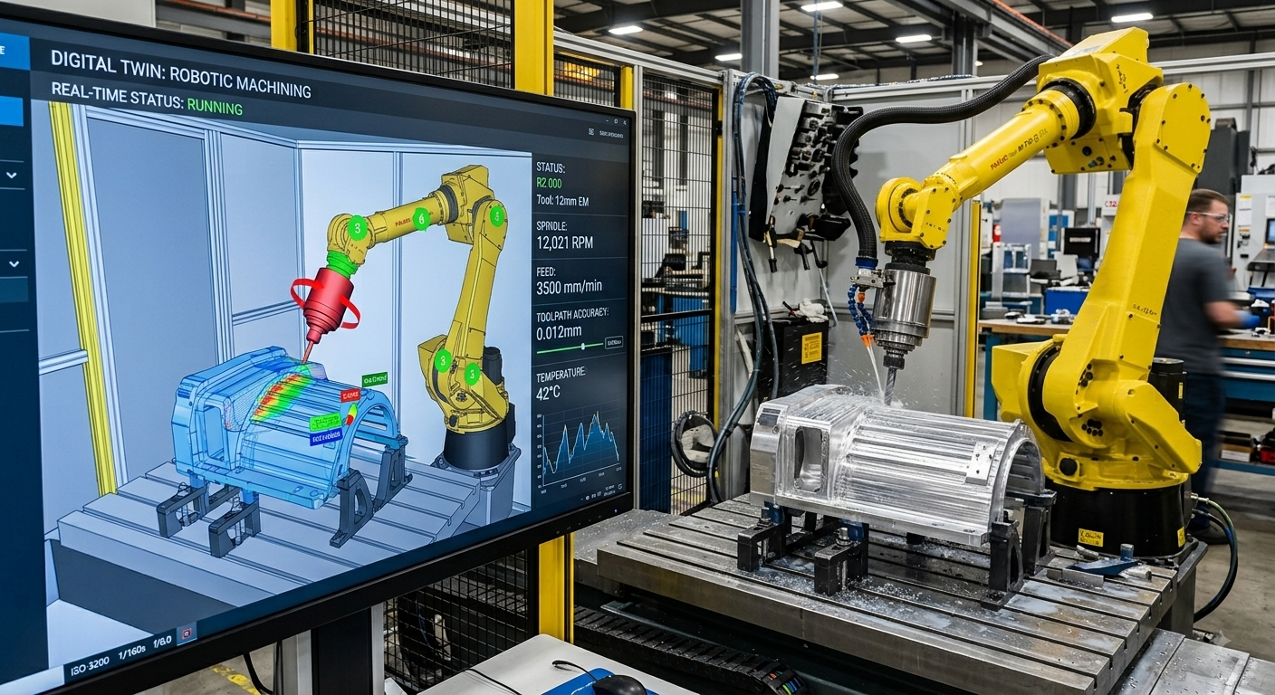

A digital twin for robotic machining can reduce collision risk and physical setup work by allowing engineers to model the robot, tool, workpiece, fixture, and surrounding equipment before running the real cell. Robot paths can then be checked virtually for interference, reach limitations, and problematic orientations before they are transferred to the shop floor.
This approach is especially useful in robotic milling, trimming, drilling, and other machining applications because the robot may follow long toolpaths around complex geometry. A path that appears valid in CAM software may still create problems when the complete robot motion, wrist orientation, fixture, and cell structure are considered.
A digital twin does not guarantee that the real installation will behave exactly like the virtual model. Its usefulness depends on the accuracy of the robot model, tooling dimensions, coordinate systems, and cell geometry. For that reason, simulation should be followed by calibration, controlled commissioning, and physical verification. Used correctly, the digital model allows many geometry and programming problems to be found before they consume production time.
What Is a Digital Twin for Robotic Machining?
In this context, a digital twin is a virtual representation of the robotic machining cell. Depending on the software and project scope, the model can include the industrial robot, spindle, end-of-arm equipment, workpiece, fixture, robot base, external axes, and nearby machinery.
More than a 3D robot model
A useful machining model must reproduce the relationships that affect robot motion. Simply placing a generic robot inside a 3D layout is not sufficient. Tool center point data, robot configuration, workpiece position, and relevant obstacles must correspond closely enough to the real installation for simulation results to be meaningful.
Relationship with offline programming
Digital twins are often used with offline programming. Engineers can prepare and test robot programs on a computer rather than creating every movement directly with the physical robot. Current simulation platforms from major robot manufacturers support virtual cell development and offline programming for this purpose.
How a Digital Twin Reduces Collision Risk
Robotic machining creates several possible collision combinations. The robot arm can contact a fixture, the spindle can approach the workpiece incorrectly, or the robot wrist can encounter surrounding equipment while trying to maintain the required tool orientation.
Checking the complete moving system
Collision analysis should therefore include more than the tool tip. Relevant robot links, spindle geometry, toolholder, cutting tool, workpiece, fixtures, and nearby structures should be represented. In applications using a positioner or linear track, the movement of those external axes must also be considered.
Testing approach and retract movements
The machining toolpath itself is only part of the robot program. Approach, departure, tool-change, and transition movements can also create interference. Simulating the complete sequence helps engineers identify where a safe cutting path becomes unsafe during movement between machining operations.
Why Robot Reach and Configuration Must Be Simulated
A target point can lie within the nominal working envelope of a robot and still be difficult to reach with the orientation required for machining. Joint limits, wrist posture, and the relationship between the robot base and workpiece influence whether the complete toolpath is practical.
Tool orientation changes robot posture.
Machining often requires the cutting tool to maintain a specific orientation relative to the surface. As the path moves around a large or complex component, the robot may need substantial joint reconfiguration. Simulation helps identify locations where an alternative tool orientation, robot position or workpiece setup should be considered.
This type of motion analysis is particularly useful while designing the cell, when moving the robot base, changing the fixture position, or adding an external axis is still possible. Robotic Hi-Tech Solutions publishes additional technical guides on robotic machining and industrial automation that examine related cell-design and process considerations.
How Digital Simulation Can Reduce Setup Time
A digital twin for robotic machining can move part of the programming and validation work away from the physical robot, although physical commissioning is still necessary. When cell geometry and process information are available early, engineers can develop toolpaths, evaluate robot positions, and investigate collisions while mechanical installation is still being prepared.
Move engineering work before installation.
Offline preparation can shift part of the programming and validation effort away from the physical cell. This is useful when the robot is already producing other parts, when the new cell has not yet been assembled or when access to production equipment is limited.
Prepare changes before stopping production.
For an existing cell, a revised workpiece, fixture, or machining program can first be evaluated in the digital environment. Engineers can identify obvious reach and interference problems before scheduling physical trials. The final program must still be checked on the actual installation because the virtual model can contain dimensional or calibration errors.
What Must Be Accurate in the Digital Model?
The reliability of a digital twin for robotic machining depends on the accuracy of the input data. A missing bracket, incorrectly positioned fixture or inaccurate tool length can create clearance in the simulation that does not exist in the physical cell.
Coordinate systems are equally important. The relationship between the robot base, tool center point, workpiece frame and any external axis must be established correctly. Small modeling discrepancies may become significant when a planned path passes close to fixtures or other cell equipment.
Eight Checks Before Using the Digital Twin for Production
Before transferring a simulated machining program to the real robot, review the model systematically. The following checks address common sources of differences between a virtual cell and its physical counterpart.
- Verify the exact robot configuration. Confirm the robot model and relevant mechanical configuration represented in the simulation correspond to the installed system.
- Check the robot base location. Compare the simulated mounting position and orientation with the physical installation because base errors affect the complete workspace.
- Validate spindle and tool geometry. Include dimensions that influence clearance, particularly the spindle body, toolholder and cutting tool.
- Confirm the tool center point. The programmed TCP should correspond to the physical tool setup used during machining.
- Check workpiece and fixture positions. Verify their coordinate systems and include clamps or other components that can intersect robot motion.
- Model relevant surrounding equipment. Include structures close enough to the robot path to create realistic collision risks.
- Simulate non-cutting motions. Review approaches, retracts, transitions, and other movements rather than checking only the machining toolpath.
- Revalidate on the physical cell. Perform controlled commissioning and correct discrepancies between the digital model and actual installation before normal production.
Why Simulation Does Not Replace Robot Safety Engineering
A digital twin for robotic machining is an engineering aid, not a substitute for machinery risk assessment or safety functions. A digital model may identify geometric interference between modeled objects, but it does not by itself demonstrate that a robotic cell complies with applicable safety requirements.
For industrial robot applications and robot cells, ISO 10218-2:2025 covers safety requirements for robot applications and integration. Machining can also introduce application-specific hazards that must be considered during system design. The applicable requirements depend on the machine, process, installation, and jurisdiction.
Physical validation remains necessary after simulation. Safety devices, interlocks, stopping functions, and other risk-reduction measures must be evaluated as part of the real integrated system rather than assumed to be correct because the virtual robot completed its path successfully.
When Is a Digital Twin Most Useful in Robotic Machining?
A digital twin for robotic machining becomes especially useful when the robot must process large or geometrically complex parts, use multiple tool orientations, coordinate with external axes or operate in a cell where clearances are limited.
It is also useful when a company expects frequent product changes. Maintaining an updated virtual representation of the cell can provide an engineering environment in which new fixtures and robot programs are evaluated before physical trials.
The benefit depends on maintaining the model. If tooling, fixtures, or cell geometry change while the digital representation remains unchanged, simulation results gradually become less representative of the actual installation.
FAQ
Can a digital twin completely prevent robot collisions?
No. It can identify collisions involving geometry and conditions represented in the model, but incorrect dimensions, missing equipment, calibration errors, or unmodeled conditions can produce different results in the real cell.
Does robotic machining require a digital twin?
No. A digital twin for robotic machining is not mandatory, but it can be useful when toolpaths are complex, physical programming time is limited or cell clearances require detailed analysis.
Can the machining toolpath be tested before the robot is installed?
Yes, if suitable robot, tooling, workpiece, and cell data are available. Offline simulation allows preliminary path and reach analysis before the complete physical installation exists.
Does a collision-free simulation mean the cell is safe?
No. Geometric collision checking and machinery safety assessment are different activities. A collision-free path does not replace safeguarding, risk assessment, or validation of safety-related functions.
Why can a simulated program need adjustment on the real robot?
The physical robot, fixture, tool and workpiece may not occupy exactly the positions represented in the digital model. Calibration and installation tolerances can therefore require adjustments during commissioning.
Can a digital twin include an external linear axis or positioner?
Yes, when the selected simulation environment supports the relevant mechanism. Modeling coordinated external axes is useful because their positions directly affect robot reach, orientation, and collision clearance.
Should the digital twin be updated after commissioning?
Yes. Updating the model when verified physical positions, tooling, or fixtures change helps preserve its usefulness for future programming and engineering work.
Who should evaluate whether a digital twin fits a machining project?
The decision should consider the robot, machining process, available CAD data, programming workflow, required external axes, and expected production changes. Companies evaluating a new robotic machining cell can contact Robotic Hi-Tech Solutions to discuss the technical requirements of the application before defining the simulation and integration scope.