English
 Italiano
 Українська
 Русский
 Español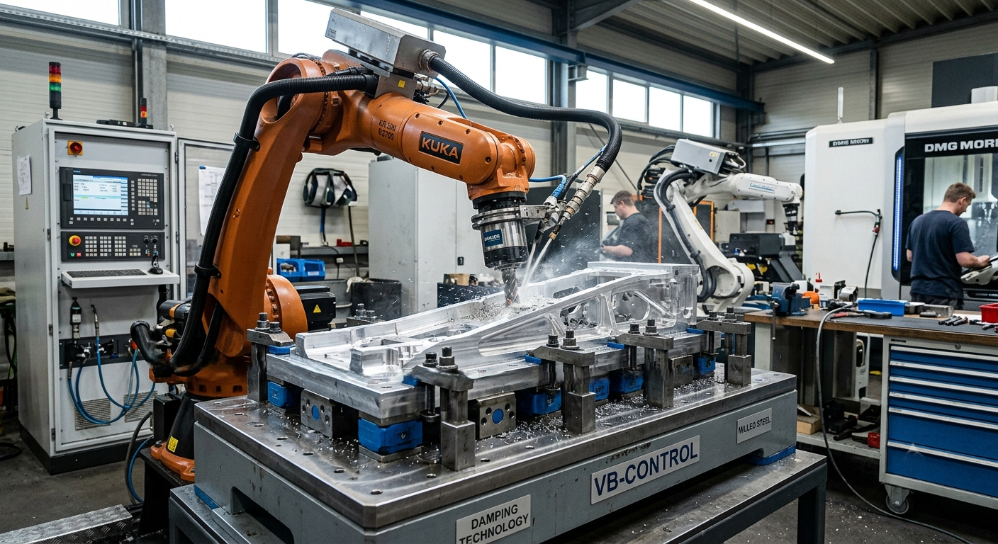

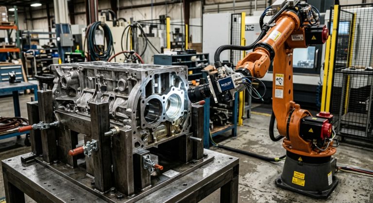
A robotic milling fixturing strategy directly influences vibration, surface finish, dimensional stability, and process repeatability. Although vibration is often associated with robot stiffness, spindle performance, or tool length, the way the workpiece is supported and clamped can be equally important.
Even a correctly calibrated industrial robot equipped with a high-speed spindle may produce unstable results when the workpiece moves, bends, or vibrates under cutting forces. For this reason, workholding should not be treated as a secondary accessory. It must be engineered as part of the complete robotic machining system.
Why a Robotic Milling Fixturing Strategy Matters
Traditional CNC machining centers normally use heavy machine beds and rigid workholding systems. By contrast, large-format robotic milling cells may use modular tables, adjustable supports, custom frames, or application-specific fixtures.
These flexible configurations make it possible to machine oversized and complex components. However, they can also introduce additional sources of movement if the fixture is not sufficiently rigid.
Fixturing becomes especially important when machining:
- Composite molds and tooling
- Large aluminum panels
- Foam and resin models
- Thin-wall structures
- Plastic and polymer components
- Oversized parts with unsupported spans
If these components are not supported correctly, cutting forces may cause local deflection or oscillation. As a result, the process can develop surface waviness, chatter marks, dimensional variation, or inconsistent material removal.
How Workpiece Movement Produces Machining Vibration
During milling, the cutting tool applies changing forces to the workpiece. These forces vary according to the tool geometry, spindle speed, feed rate, depth of cut, material, and toolpath direction.
If the fixture cannot resist those forces, the workpiece may move slightly between tool engagements. Even small movements can affect the interaction between the cutting edge and the material.
This movement may produce:
- Visible vibration marks on the machined surface
- Inconsistent cutting depth
- Local dimensional deviations
- Premature tool wear
- Reduced finishing quality
- Longer setup and rework times
However, not every vibration problem originates in the fixture. Robot posture, spindle condition, tool overhang, cutting parameters, and cell foundation can also contribute. Therefore, vibration should be evaluated as a system-level problem rather than attributed to one component alone.
Key Elements of a Robotic Milling Fixturing Strategy
An effective robotic milling fixturing strategy must control the workpiece without damaging or deforming it. Several engineering factors should be evaluated during fixture design.
1. Support distribution
Large surfaces require properly distributed support. When support points are concentrated only around the perimeter, the center of the component may remain flexible.
Additional support beneath long spans can reduce bending and local movement. Nevertheless, support points must match the geometry of the part and should not create unwanted deformation.
2. Fixture stiffness
The fixture must resist the dynamic forces generated during machining. A fixture may appear stable during installation but still deform under cutting loads.
For demanding applications, engineers may evaluate fixture stiffness through structural calculations, simulation, or physical testing. The objective is to identify areas where the fixture or workpiece could move during roughing and finishing operations.
3. Clamping-force control
More clamping force does not always produce better results. Excessive force can deform thin panels, composite structures, or lightweight components.
The required force should secure the workpiece while preserving its intended geometry. Clamping pressure may also need to be distributed across several points instead of being concentrated in one area.
4. Part geometry
Complex components may require dedicated locating surfaces, contour supports, or multi-point anchoring. Standard clamps may not provide enough contact for curved, irregular, or asymmetric parts.
In these cases, custom fixtures can improve repeatable positioning and reduce unsupported areas.
5. Cutting-force direction
Support and clamping points should be positioned with the expected cutting-force direction in mind. A fixture that resists vertical loading may still be vulnerable to lateral forces.
Toolpath planning and fixture design should therefore be coordinated. This is particularly important when the robot machines the same component from multiple orientations.
Fixture design must also support safe access during setup, inspection, and maintenance. According to the Occupational Safety and Health Administration’s robotics guidance, many robot-related incidents occur during non-routine operations such as programming, testing, setup, adjustment, and maintenance. Therefore, clamp locations, access points, and fixture components should be coordinated with the cell’s guarding, safety procedures, and robot working envelope.
Large-Format Milling Stability Challenges
A well-planned robotic milling fixturing strategy becomes especially important in large-format machining. As the distance between support points increases, both the workpiece and the fixture become more vulnerable to bending, movement, and vibration.
Common challenges include:
- Unsupported central areas
- Long structural spans
- Flexible or thin-wall components
- Irregular mold geometries
- Porous materials that reduce vacuum performance
- Thermal expansion across large components
- Restricted access around clamps and supports
Furthermore, oversized parts may require the robot to work at different reaches and postures. Because robot stiffness changes across the working envelope, workpiece stability should be considered together with robot configuration and toolpath planning.
Mechanical, Vacuum, and Hybrid Clamping
Different workpieces require different workholding methods. The best solution depends on the component material, geometry, cutting forces, and required access.
The selected clamping method should therefore support the complete robotic milling fixturing strategy. Engineers must evaluate not only holding force but also part deformation, machining access, sealing conditions, and resistance to cutting loads.
Mechanical clamping
Mechanical clamps can provide strong and predictable holding forces. They are commonly used for rigid components and fixtures with defined locating points.
However, clamp positions must be planned carefully. Poorly positioned clamps can obstruct the toolpath or concentrate force in sensitive areas.
Vacuum clamping
Vacuum systems can distribute holding pressure across a relatively large surface. They can also provide good tool access because fewer mechanical clamps are required.
Nevertheless, vacuum performance depends on surface sealing, material porosity, available contact area, and the forces generated during machining. Vacuum clamping should not automatically be assumed to be sufficient for every composite, foam or polymer component.
Hybrid clamping
A hybrid system combines vacuum holding with mechanical stops, locating pins or additional clamps. This configuration can improve resistance to lateral movement while maintaining broad surface support.
Hybrid solutions are often useful for large components that require both distributed holding pressure and positive mechanical restraint.
How Fixturing Supports Robotic Milling Accuracy
A stable robotic milling fixturing strategy helps maintain consistent workpiece positioning throughout roughing, semi-finishing, and finishing operations. When the fixture limits movement without deforming the component, the robot can follow the programmed toolpath under more predictable cutting conditions.
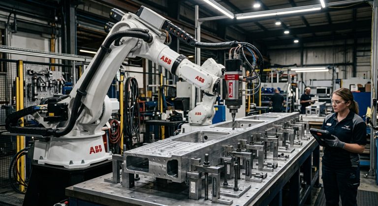
When a cell uses robots from manufacturers such as KUKA, ABB, or FANUC, the fixture must be coordinated with the selected robot model, spindle package, and machining envelope. However, the robot brand alone does not determine the correct workholding solution.
The complete integration process should consider:
- Robot reach and posture throughout the toolpath
- Spindle weight and cutting-force capacity
- Tool length and toolholder configuration
- Workpiece loading and unloading requirements
- Operator access and ergonomic conditions
- Fixture inspection and maintenance
- Dust, chip, and coolant management
- Safety-system placement
Digital simulation can help identify access limitations and potential collisions. However, physical validation remains important because the real fixture, material, and cutting process may behave differently from the initial model.
How to Validate a Fixture Before Production
A fixture should be validated under representative machining conditions. Visual inspection alone cannot confirm whether the system will remain stable during cutting.
A practical validation process may include:
- Inspecting all fixture connections and support points.
- Checking that the part is seated correctly against its locating surfaces.
- Measuring workpiece or fixture deflection under controlled loading.
- Running conservative test passes before full-depth machining.
- Monitoring vibration, sound, and surface condition.
- Inspecting critical dimensions after roughing.
- Adjusting supports or cutting parameters when necessary.
- Confirming repeatability across multiple loading cycles.
For high-value components, engineers may also use displacement sensors, accelerometers, or metrology equipment to evaluate movement. The required validation method will depend on the tolerance, material, and production risk.
Technical Checklist for Vibration-Optimized Fixturing
- Is support distributed across all critical areas of the workpiece?
- Are long spans or central areas adequately supported?
- Can the fixture resist vertical and lateral cutting forces?
- Are clamping forces sufficient without deforming the component?
- Are support points aligned with the expected load direction?
- Has fixture stiffness been evaluated under representative loads?
- Does the fixture allow access to every required machining area?
- Are clamps positioned outside the robot and tool collision zones?
- Has vibration been monitored during test passes?
- Has fixture or workpiece deflection been checked before finishing?
- Can the setup be reproduced consistently for the next component?
Benefits of a Stable Workholding System
A properly engineered fixture can contribute to better machining performance throughout the production cycle.
Potential benefits include:
- Improved surface consistency
- More stable dimensional results
- Reduced risk of chatter
- More predictable tool engagement
- Lower probability of workpiece movement
- Reduced rework and manual finishing
- Improved process repeatability
These improvements do not depend on fixturing alone. Cutting parameters, robot configuration, spindle performance, tooling, and programming must also be optimized. However, a weak workholding system can limit the performance of an otherwise well-engineered robotic cell.
FAQ’s
Can poor fixturing affect geometric tolerances?
Yes. Workpiece movement or deflection can affect flatness, parallelism, profile accuracy, and other geometric characteristics. The actual effect depends on the component geometry, support conditions, and cutting forces.
Is vacuum clamping sufficient for composite machining?
It can be sufficient in some applications, but its performance depends on material porosity, sealing quality, available surface area, and machining forces. Testing is recommended before production.
Can excessive clamping force deform a workpiece?
Yes. Thin panels, composite parts, and lightweight structures can deform when clamping pressure is excessive or poorly distributed.
Should fixture design be included during robotic integration?
Yes. Fixture design should be coordinated with the robot envelope, spindle, toolpath, workpiece loading process, and safety layout.
Does a rigid fixture eliminate all robotic milling vibration?
No. A rigid fixture reduces one potential source of instability. Robot posture, tooling, spindle condition, cutting parameters, and foundation stiffness must also be evaluated.
How can fixture deflection be detected?
Depending on the application, engineers may use mechanical indicators, displacement sensors, metrology equipment, vibration sensors, or controlled machining tests.
How often should a robotic milling fixture be inspected?
The fixture should be inspected before critical production runs and at regular maintenance intervals. Engineers should check clamps, locating points, fasteners, support surfaces, and structural connections for wear, looseness, or deformation.
Can the same fixture be used for roughing and finishing operations?
Yes, provided that the fixture maintains sufficient stiffness and positioning accuracy throughout both stages. However, finishing may require additional support, lower cutting forces, or a fixture-deflection check after roughing.
How does fixture repeatability affect robotic milling accuracy?
Fixture repeatability determines whether each workpiece returns to the same position and support condition. Inconsistent loading or locating can create dimensional variation even when the robot follows the same programmed toolpath.
When should a robotic milling fixturing strategy be reviewed?
A robotic milling fixturing strategy should be reviewed whenever the workpiece material, geometry, cutting tool, machining orientation, or cutting parameters change. It should also be reassessed when vibration, dimensional variation, or inconsistent surface quality appears during production.
Conclusion
A reliable robotic milling fixturing strategy is essential for controlling workpiece movement in large-format machining. Support distribution, fixture stiffness, clamping pressure, and cutting-force direction all influence the stability of the process.
The fixture should therefore be treated as an active part of the machining system. When workholding is engineered together with the robot, spindle, tooling, and toolpath, manufacturers can achieve more consistent surfaces, dimensions, and production results.
Engineer a More Stable Robotic Milling Process
Robotic Hi-Tech Solutions designs and integrates large-format robotic milling cells for complex industrial components. Each project considers not only the robot and spindle, but also the structural frame, workpiece support, fixture configuration, and machining requirements.
If your application involves oversized molds, composite tooling, aluminum structures, or difficult-to-support components, our engineering team can develop a robotic machining solution focused on access, stability, and repeatable performance.
Contact Robotic Hi-Tech Solutions to discuss the technical requirements of your robotic milling application. “`