English
 Italiano
 Українська
 Русский
 Español
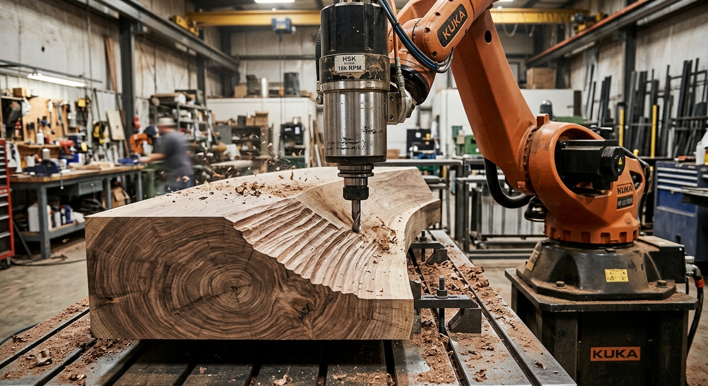

Wood carving anisotropy matters because wood responds differently to cutting forces depending on fiber orientation and grain direction. Its fibers, growth rings, and internal structure influence how a rotating tool removes material. In robotic carving, these differences can affect surface quality, cutting resistance, and the risk of tearing fibers from the workpiece.
A robot may follow a geometrically accurate toolpath while producing different finishes across the same wooden component. Cutting parallel to the grain can behave differently from cutting across it. Curved surfaces make this problem more complicated because the relationship between tool movement and fiber direction changes continuously.
Understanding these variations helps engineers select cutting directions, adjust tool engagement, and develop machining strategies suited to the material. This article explains how wood structure influences robotic carving, why certain surface defects appear, and how to evaluate machining conditions before production. It also examines the interaction between grain direction, robot stiffness, cutting tools, and workpiece preparation. The objective is to make robotic wood carving more predictable without assuming that one machining strategy works for every species or geometry.
What causes wood carving anisotropy?
Wood fibers and directional properties
Wood is anisotropic because its mechanical properties depend on direction. Its three principal material directions are longitudinal, radial, and tangential. The longitudinal direction generally follows the fibers, while the other directions relate to the growth rings.
These structural differences influence cutting resistance and fracture behavior. A cutter may separate fibers along their length or sever them across their orientation. Consequently, identical cutting parameters can produce different chip formation and surface characteristics.
Why growth rings influence machining
Growth rings contain regions with different anatomical characteristics and densities. Their arrangement varies between species and individual boards. When a cutter crosses these regions, local cutting conditions can change, potentially creating variations in texture or material removal.
Engineers should therefore inspect grain patterns before generating finishing paths, particularly when the component includes visible decorative surfaces.
How grain direction changes cutting behavior
Cutting along and against the grain
Wood carving anisotropy influences how cutting direction affects fiber separation and surface quality. Machining along the grain can produce a clean surface when the cutting direction supports controlled fiber separation. However, cutting against rising grain may lift fibers ahead of the cutting edge, producing tear-out or rough patches.
The result also depends on cutter rotation, edge geometry, engagement, and wood condition. Following the grain is not automatically the best approach in every rotary milling operation.
Cross-grain and end-grain machining
Cross-grain machining severs fibers rather than primarily separating them lengthwise. End-grain cutting presents another engagement condition because the tool acts across fiber ends. Both operations can require different parameters from longitudinal cutting.
Research on wood-cutting mechanics shows that grain direction influences cutting forces and chip formation. Curti et al. (2018), in their study Effect of grain direction on cutting forces and chip geometry during green beech wood machining, examined how fiber orientation affects machining behavior. Although the research focuses on orthogonal cutting rather than robotic milling, its findings provide useful context for understanding directional material responses in wood carving.
How anisotropy affects robotic surface quality
Fiber tear-out and surface roughness
Fiber tear-out occurs when material separates beyond the intended cutting boundary. It can appear near changing grain directions, knots, or areas where fibers approach the surface at unfavorable angles.
Wood carving anisotropy helps explain why rough patches sometimes appear despite consistent programmed tool movement. Before changing the robot program, operators should examine whether defects follow the grain pattern or the machining path.
Tool marks on curved wooden surfaces
Wood carving anisotropy becomes particularly relevant on curved surfaces, where contact angles between the cutter and workpiece continually change. Even when the robot maintains consistent tool spacing, the local grain orientation may change along the path.
Engineers can compare alternative finishing directions and tool orientations using representative test pieces. The article on tool orientation and surface finish explains how cutting-force direction and tool positioning influence machining quality.
Why robot stiffness matters during wood carving
Cutting forces and robot deflection
Industrial robots generally exhibit posture-dependent stiffness. Their resistance to cutting forces changes with joint configuration, tool orientation, and the direction of the applied load.
When grain orientation changes cutting resistance, the resulting forces can interact with robot compliance. This interaction may produce local deviations or vibration, especially during heavy material removal.
Managing unstable machining positions
Engineers should identify positions where the robot approaches unfavorable configurations or operates with extended reach. These positions may require lighter cutting passes or alternative tool orientations.
The relationship between posture, vibration, and finish is examined further in robot dynamics in large-format robotic milling. Material behavior and mechanical stiffness should be evaluated together rather than treated as unrelated problems.
How toolpath planning can account for wood grain
Choosing machining directions
Wood carving anisotropy should be considered when generating toolpaths for complex wooden components. Conventional CAM software primarily generates paths from geometry, machining boundaries, and selected cutting strategies. It does not necessarily understand the internal fiber orientation of a wooden workpiece.
For decorative panels or sculptural components, programmers can divide surfaces into machining regions according to observed grain direction. Different regions may benefit from different finishing passes, provided the robot can execute the transitions safely. Accounting for wood carving anisotropy during toolpath planning can help reduce grain-related surface defects.
Adjusting engagement and finishing passes
Reducing cutting engagement can help limit forces where tear-out or unstable machining occurs. However, excessively light passes may introduce rubbing or inefficient cutting, depending on the tool and operating conditions.
Wood carving anisotropy should therefore influence parameter selection without replacing machining trials. Engineers need to evaluate cutting depth, feed rate, spindle speed, and surface results together.
How cutting tools influence material response
Cutting-edge geometry and sharpness
Sharp cutting edges support controlled fiber separation. Worn or damaged edges can increase friction, compress fibers, and worsen surface defects. Tool geometry also influences chip formation and the forces transmitted to the robot.
Tool selection should consider wood species, expected grain variation, machining depth, and surface geometry. A cutter that performs well during roughing may not provide the required finish on exposed decorative surfaces.
Tool orientation and chip evacuation
Tool orientation affects contact conditions and the direction in which chips leave the cutting zone. Poor chip evacuation may interfere with cutting or obscure surface defects during inspection.
Wood dust also requires appropriate extraction and exposure controls. Extraction equipment should suit the generated dust, process conditions, and applicable safety requirements.
How wood preparation affects carving consistency
Moisture content and dimensional stability
Wood moisture content influences its mechanical behavior and dimensions. Moisture changes can produce swelling or shrinkage, particularly across the grain. This can affect dimensional consistency before and after machining.
Workpieces should be conditioned appropriately for their intended environment. Engineers should also check whether material movement after unclamping could affect assembly or finishing requirements.
Knots, grain deviation, and laminated stock
Wood carving anisotropy can become more difficult to manage around knots and irregular grain, which interrupt otherwise consistent cutting behavior. Laminated wood products introduce additional considerations, including layer orientation, adhesive lines, and differences between constituent materials.
Material inspection should identify these features before machining. For visible architectural components, board orientation and material selection can be as important as adjustments made during robotic programming.
Practical checklist for robotic wood carving
Evaluating wood carving anisotropy requires material inspection, toolpath analysis, and representative machining tests. The following checks help identify potential problems before machining a complete architectural or sculptural component.
- Identify the wood species: Record the material and examine its expected machining behavior rather than applying settings from unrelated wood products.
- Inspect grain direction: Mark visible fiber orientation and identify regions with knots, reversing grain, or irregular growth patterns.
- Check moisture condition: Measure moisture content using a suitable method and compare it with the requirements of the intended application.
- Review workpiece orientation: Position the material so critical surfaces remain accessible and cutting directions can be evaluated.
- Evaluate cutting tools: Inspect edge condition, tool geometry, clamping, and suitability for the selected wood.
- Test alternative toolpaths: Compare cutting directions on representative areas, especially where grain orientation changes.
- Monitor machining stability: Observe vibration, cutting sound, workpiece movement, and visible defects across different robot positions.
- Inspect finished surfaces: Check tear-out, dimensional accuracy, machining marks, and any changes after unclamping.
Documenting these observations helps distinguish material-related defects from programming or mechanical problems. It also provides a reference when subsequent workpieces show different machining behavior.
Frequently Asked Questions
What does anisotropy mean in wood carving?
Anisotropy means wood has direction-dependent properties. Its fibers and growth-ring structure influence cutting resistance, chip formation, and the resulting surface quality.
Why does wood grain direction affect robotic carving?
Grain direction changes how the cutter separates or severs fibers. Depending on the cutting conditions, this can influence forces, tear-out, and surface texture.
Can robotic toolpaths compensate for wood anisotropy?
Toolpaths can account for observed grain direction through changes in cutting strategy, engagement, and orientation. However, programming cannot eliminate natural material variation.
Is cutting along the grain always better?
No. The preferred direction depends on fiber orientation, cutter geometry, rotation, and surface requirements. Representative machining tests help establish suitable conditions.
Does wood moisture affect robotic carving accuracy?
Yes. Moisture influences wood dimensions and mechanical behavior. Changes before or after machining may affect the finished geometry, especially across the grain.
Can robot stiffness influence wood carving quality?
Yes. Robot compliance can interact with changing cutting forces. Depending on posture and tool engagement, this may contribute to vibration or dimensional variation.
Are laminated wood panels easier to machine than solid wood?
Not necessarily. Some engineered products offer greater material uniformity, but layer orientation, adhesive lines, and product construction can introduce different machining challenges.
How should engineers validate a robotic wood carving process?
They should test representative material, grain orientations, cutting parameters, and robot positions. Inspection should cover surface defects, dimensional results, and process stability.
For architectural components or complex wooden sculptures, the machining strategy should reflect both material behavior and robotic cell capabilities. Engineers evaluating a specific application can contact Robotic Hi-Tech Solutions to discuss workpiece geometry, material selection, and machining requirements before defining a production approach.