English
 Italiano
 Українська
 Русский
 Español
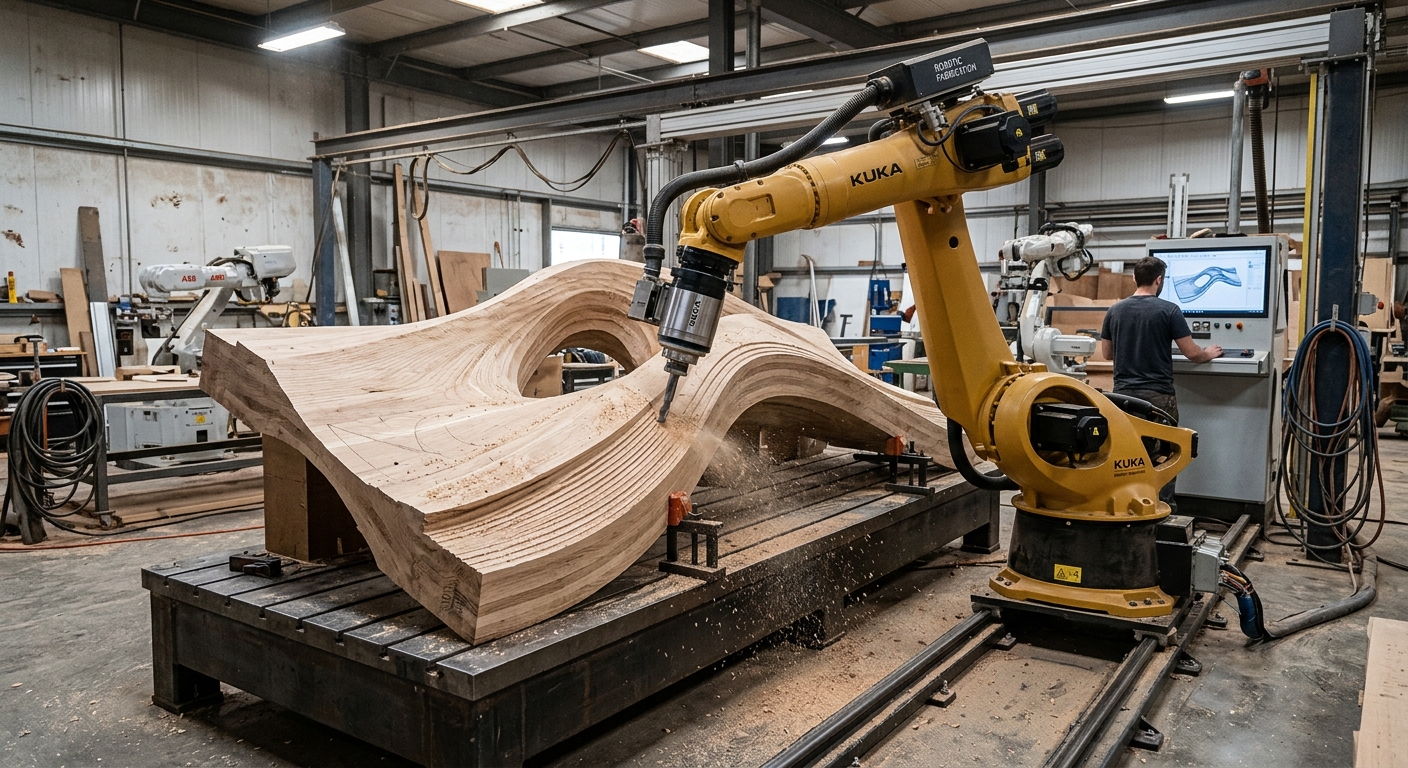

Architects design parts for robotic fabrication by considering manufacturing constraints while developing the geometry. They evaluate robot reach, tool access, material behavior, component dimensions, and assembly requirements before finalizing each part. This approach helps prevent designs that appear correct digitally but cannot be manufactured with the available robotic system.
Robotic fabrication design connects architectural modelling with production planning. Instead of treating manufacturing as a separate stage, architects define shapes that suit the selected process. Curved panels, sculptural surfaces, customized façade elements, and complex moulds may require different geometric strategies depending on how the robot will produce them.
The process involves more than generating a toolpath from a digital model. Architects must understand how the robot approaches each surface, how the workpiece remains supported, and how individual parts connect after fabrication. This article explains how those decisions influence geometry, materials, tolerances, manufacturing sequences, and the final architectural assembly.
1. How robotic fabrication design influences architectural geometry
Designing geometry around manufacturing capabilities
Architectural geometry must suit the intended fabrication method. A curved panel suitable for robotic milling may require different features from a component produced through additive manufacturing. Architects therefore evaluate surface curvature, material thickness, edge conditions, and available manufacturing directions before approving the geometry.
For example, a deeply recessed surface may prevent a milling tool from reaching the required area. Modifying the recess or dividing the component can improve accessibility without necessarily changing the overall architectural concept.
Using parametric constraints during design
Parametric modelling allows architects to control geometry through adjustable dimensions and relationships. These models can incorporate manufacturing constraints, including minimum material thickness, maximum component dimensions, and permissible curvature.
The relationship between digital geometry and executable movement is examined further in the article on the parametric robot workflow. This distinction helps architects understand why a valid digital model still requires manufacturing preparation.
2. How architects account for robot reach and tool access
Evaluating the working envelope
In robotic fabrication design, the robot’s working envelope determines which areas of a component can be reached. However, reachability also depends on tool orientation, robot configuration, and surrounding equipment. Architects should not assume that every surface inside the nominal working envelope is accessible.
Large architectural components may require repositioning, an external linear axis, or subdivision into smaller parts. Each option affects the manufacturing setup and subsequent assembly.
Considering tool orientation and clearance
Tool orientation influences whether a robot can machine, deposit, or finish a particular surface. Deep cavities, narrow openings, and closely spaced features may restrict the movement of the end effector.
Architects can improve access by adjusting local geometry, introducing suitable openings, or changing component orientation. Robot simulation should then verify the proposed movements, including approach paths and collision clearance.
3. How material selection changes robotic part design
Matching geometry to material behavior
Material selection directly influences robotic fabrication design because different materials respond differently to cutting, deposition, forming, and handling. Timber may exhibit grain-dependent machining behavior, while foam, polymers, and composites introduce different processing constraints.
Architects should consider how the selected material responds to the intended operation. Thin sections, unsupported edges, and delicate features may require additional support or geometric modification during fabrication.
Planning for material removal or deposition
Subtractive processes remove material from a workpiece. Architects must provide sufficient stock for machining and consider whether cutting tools can access the intended surfaces.
Additive processes build geometry through deposited material. Their design constraints may involve layer support, deposition direction, material flow, and curing or cooling behavior. The same architectural form may therefore require different preparation for each process.
4. Why component subdivision matters in architectural fabrication
Dividing large architectural elements
Component subdivision is an important consideration in robotic fabrication design when architectural elements exceed available material stock, robot reach, transport dimensions, or handling capacity. Architects can address these limitations by dividing the geometry into smaller manufacturing units.
Subdivision requires more than selecting convenient cutting planes. Each separation affects visible surfaces, structural connections, alignment, and installation. Related considerations appear in the guide to robotic sculpture fabrication and component subdivision.
Designing connections before manufacturing
Connections should be defined before finalizing individual parts. Architects must consider assembly access, fastening methods, alignment references, and the space required for installation tools.
For example, two curved panels may fit together geometrically but leave insufficient room for fastening equipment. Reviewing assembly operations during design helps identify these conflicts before manufacturing begins.
5. How tolerances and surface quality affect component geometry
Defining realistic dimensional requirements
Manufacturing tolerances describe acceptable dimensional variation. Architects should distinguish between surfaces requiring precise alignment and surfaces where greater variation is acceptable.
Robotic fabrication accuracy depends on several factors, including calibration, tooling, fixtures, robot configuration, and material behavior. Designers should therefore establish dimensional requirements through process evaluation rather than assuming that digital precision guarantees physical accuracy.
Preparing surfaces for finishing operations
Surface quality depends partly on toolpath spacing, cutting direction, tool geometry, and material response. A smooth digital surface may show visible machining marks after fabrication.
Architects should identify visible surfaces and define appropriate finishing requirements. Where necessary, the manufacturing plan can include additional machining, sanding, coating, or other finishing operations.
6. How architects translate design models into robot instructions
Preparing geometry for manufacturing software
Architectural CAD models describe the intended component geometry. Manufacturing software uses that geometry to calculate operations and generate toolpaths suitable for the selected process.
Toolpaths must account for tool dimensions, movement direction, workpiece coordinates, and process conditions. The resulting information requires conversion into instructions compatible with the robot controller.
Validating movements before production
Simulation helps engineers examine robot reachability, joint movement, tool orientation, and potential collisions. It can also reveal situations where a geometrically acceptable path produces an unsuitable robot configuration.
For projects involving existing architectural surfaces, the article on 3D scanning and robotic machining of architectural surfaces explains how captured geometry becomes manufacturing information. Physical tests remain necessary because simulation cannot reproduce every material or process effect.
7. What architects should verify before releasing a part for fabrication
A structured robotic fabrication design review helps architects identify conflicts between geometry, equipment, and installation requirements. The following checks should be completed with the fabrication team before approving production files.
- Component dimensions: Compare the complete part with material stock dimensions, fixture capacity, and available robot reach.
- Tool accessibility: Identify recessed surfaces, narrow openings, and features that restrict tool orientation.
- Material compatibility: Verify that the selected material suits the planned cutting, deposition, or forming process.
- Minimum feature dimensions: Check thin walls, narrow edges, and delicate details against the selected manufacturing method.
- Connection geometry: Confirm joint positions, fastening access, alignment features, and assembly clearances.
- Dimensional tolerances: Define acceptable variation for critical interfaces and visible architectural surfaces.
- Manufacturing simulation: Review robot configurations, collisions, fixture interference, and tool approach movements.
- Inspection requirements: Establish how finished dimensions, surface conditions, and assembly interfaces will be checked.
These checks should reflect the actual robot cell rather than generic equipment capabilities. Changes to tooling, fixtures, or material stock may require another design review.
8. How robotic fabrication design supports architectural production
Coordinating designers and fabrication engineers
Architects define the intended geometry and functional requirements, while fabrication engineers evaluate process feasibility. Early coordination allows both teams to resolve manufacturing restrictions before they become expensive design changes.
Robotic fabrication design works best when component geometry, manufacturing data, and assembly requirements remain connected. Recording design revisions also helps teams identify which manufacturing files correspond to each approved component.
Testing representative components
A representative prototype can reveal machining marks, geometric deviations, material deformation, or assembly difficulties that digital models cannot fully predict.
Architects should inspect the prototype against agreed acceptance criteria. If results require modification, the team can revise geometry, tooling, fixtures, or processing parameters before releasing the remaining components.
For architectural projects requiring robotic machining or fabrication planning, contact Robotic Hi-Tech Solutions to discuss component geometry, tooling requirements, and potential system configurations. Workplace safety requirements should also be assessed using applicable regulations and technical guidance, including the OSHA guidance on industrial robot systems and safety.
Frequently Asked Questions
Can architects design robotic fabrication parts using conventional CAD software?
Yes. Conventional CAD software can create the geometry, but additional manufacturing preparation and robot programming are generally required before production.
Does every architectural component need parametric modelling?
No. Parametric modelling is useful when components share adjustable relationships or require controlled variation. Fixed geometry can also support robotic manufacturing.
Why must architects consider robot reach during design?
Robot reach affects component dimensions, manufacturing orientation, and tool accessibility. Some features may require repositioning or subdivision.
Can robotic fabrication produce different architectural components?
Yes. A robotic system can manufacture different geometries when compatible tooling, programs, materials, and process conditions are available.
How do architects determine suitable manufacturing tolerances?
They evaluate functional requirements, connection geometry, manufacturing capability, and physical test results before defining acceptable dimensional variation.
Can a robot manufacture every curved architectural surface?
No. Tool accessibility, robot kinematics, material behaviour, and equipment limitations can prevent certain geometries from being manufactured directly.
Why are prototypes useful before full production?
Prototypes allow teams to inspect dimensional accuracy, surface quality, material response, and assembly conditions under representative manufacturing settings.
What information should architects provide to robotic fabrication engineers?
They should provide approved geometry, material requirements, dimensional tolerances, connection details, surface specifications, and relevant installation constraints.