English
 Italiano
 Українська
 Русский
 Español
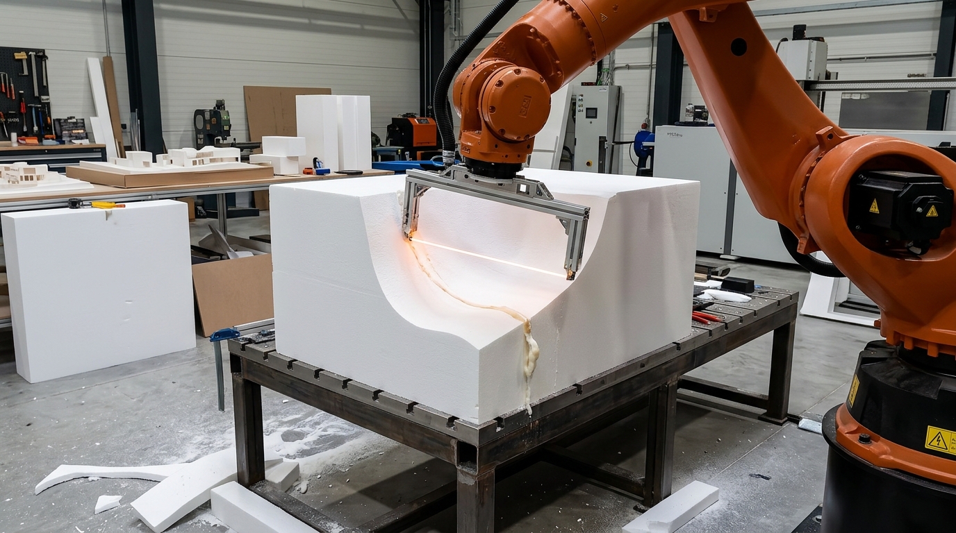

Robotic hot-wire cutting allows manufacturers to shape architectural foam using a heated wire guided by an industrial robot. The process is suitable for selected thermoplastic foams and can produce curved profiles, decorative elements, and large-scale forms. However, successful cutting depends on material compatibility, wire geometry, temperature control, and toolpath design.
Unlike conventional milling, robotic hot-wire cutting removes material through localized heating rather than mechanical cutting forces. This reduces mechanical loading on the workpiece but introduces thermal effects that influence dimensional accuracy and surface quality. Wire deflection, excessive heat, and unsuitable movement speeds can affect the finished geometry.
Architectural manufacturers must therefore evaluate the complete process before selecting a robotic cell. This guide explains how heated-wire cutting works, which shapes are practical, how toolpaths should be programmed, and where the technology reaches its limits. It also examines fixture design, inspection methods, and safety requirements for production environments.
How robotic hot-wire cutting works
Heating and material removal
A hot-wire cutting system passes electrical current through a resistive wire, generating heat. When the heated wire moves through compatible foam, the material softens or melts along the cutting path. The robot controls the position and orientation of the cutting assembly.
The wire must maintain sufficient heat to cut without excessive material removal. Cutting speed, wire temperature, foam density, and contact length interact. Consequently, settings established for one foam block may require adjustment when the material or geometry changes.
Robotic hot-wire cutting requires coordinated control of wire temperature and robot movement to maintain consistent cutting conditions.
Robot and cutting tool configuration
A typical system combines an industrial robot, wire-support frame, electrical heating equipment, workpiece fixture, and programmed motion sequence. The cutting frame must provide suitable wire tension while allowing the robot to reach the required cutting positions.
Tool dimensions also influence accessibility. A long cutting wire can process wider sections, but its support frame may restrict movement around complex surfaces. Designers must consider the entire tool assembly during collision checking.
Which architectural foam materials can be cut?
Expanded and extruded polystyrene
Expanded polystyrene (EPS) and extruded polystyrene (XPS) are commonly associated with heated-wire cutting. Their thermoplastic behavior permits controlled thermal separation. However, differences in density, formulation, and manufacturing characteristics can change cutting behavior.
Architectural applications include decorative profiles, mold patterns, sculptural components, and foam cores. The selected material must also meet the dimensional, structural, finishing, and fire-performance requirements of the intended application.
Materials that require another process
Not every architectural foam is suitable for hot-wire cutting. Thermoset materials, including many polyurethane foams, do not melt in the same manner as polystyrene. Heating unsuitable materials may cause decomposition, hazardous emissions, or poor cutting results.
Material identification must precede process selection. Manufacturers should review supplier documentation, safety data sheets, and processing recommendations rather than assuming that every foam can be cut using heat.
Toolpath design for architectural geometry
Converting CAD geometry into robot motion
Toolpath preparation begins with a digital model of the architectural component. Programming software translates the required cutting surfaces into robot positions and orientations. The resulting path must account for wire length, tool geometry, workpiece placement, and robot accessibility.
In robotic hot-wire cutting, toolpath planning must also account for wire orientation and the geometry of the cutting frame.
Unlike a rotating milling cutter, a straight heated wire removes material along its engaged length. Therefore, a conventional milling toolpath cannot simply be transferred to a hot-wire system without evaluating the resulting cut geometry.
Managing curves and surface transitions
Curved architectural profiles require coordinated motion between the robot and the cutting tool. Smooth transitions help maintain continuous cutting conditions and reduce sudden changes in wire loading or contact length.
Sharp internal corners, inaccessible recesses, and complex undercuts may require additional cuts or another manufacturing method. Designers should evaluate these limitations before finalizing the architectural model.
Wire orientation and cutting direction
The orientation of the wire determines which portion of the foam is removed during movement. Incorrect orientation can produce unintended surfaces even when the programmed robot path appears geometrically correct.
For related examples of robotic foam fabrication, the article RoboChop by Reed Kram describes a robotic installation that uses heated-wire cutting to create customized foam sculptures.
What limits cutting accuracy and surface quality?
Thermal kerf and dimensional deviation
The kerf is the width of material removed during cutting. In hot-wire applications, this width depends on the wire and surrounding thermal effects. Excessive heating or slow movement can increase material removal beyond the intended profile.
In robotic hot-wire cutting, these thermal effects must be considered when defining dimensional tolerances.
Compensation should be established through representative cutting trials. Measuring the finished profile allows programmers to adjust tool offsets and processing parameters before producing larger architectural components.
Wire deflection and tool stiffness
Wire tension and support-frame stiffness influence cutting accuracy. A wire can deflect when cutting resistance changes, particularly during demanding movements or when processing substantial material thickness.
These effects become relevant when the design requires consistent dimensions across long profiles. A rigid tool assembly and controlled cutting conditions help reduce variation, although they cannot eliminate every thermal or mechanical deviation.
How to plan an efficient cutting sequence
Cutting order and workpiece stability
Cutting order affects the stability of the remaining foam. Removing a large supporting section too early can allow the workpiece to shift, reducing accuracy during subsequent operations. For robotic hot-wire cutting, preserving workpiece stability throughout the sequence helps prevent unintended movement.
Programmers should identify supporting regions, determine which cuts release individual sections, and preserve stable reference surfaces where possible. Fixtures must secure the material without obstructing the wire or deforming the foam.
Simulation before production
Robot simulation helps identify reach limitations, tool-frame collisions, unfavorable joint configurations, and inaccessible cutting positions. However, geometric simulation alone does not establish the thermal behavior of the process.
Physical cutting trials remain necessary to assess surface quality and dimensional deviation. The published article ABB YuMi robot creates foam sculptures provides another example of robotic hot-wire fabrication involving complex three-dimensional forms.
Practical checklist for robotic foam cutting
Before approving a robotic hot-wire cutting process, engineers should evaluate the material, geometry, equipment, and production requirements. The following checks provide a practical starting point.
- Confirm foam compatibility: Identify the polymer, density, and manufacturer-approved processing conditions.
- Review geometric accessibility: Check whether the wire can reach every cutting surface without intersecting unwanted material.
- Verify robot reach: Include the cutting frame, wire length, and required orientations in the workspace assessment.
- Assess wire tension: Inspect the support mechanism and determine whether deflection could affect the required profile.
- Establish cutting parameters: Test heating settings and travel speeds using representative foam samples.
- Plan workpiece fixation: Prevent movement while preserving access to the programmed cutting surfaces.
- Simulate the complete sequence: Examine robot motion, tool clearance, cutting order, and released foam sections.
- Inspect sample components: Measure critical dimensions, kerf effects, and surface consistency before production approval.
Safety and environmental considerations
Thermal emissions and ventilation
Heating foam can generate vapors and decomposition products. Their composition depends on the polymer, temperature, and processing conditions. Appropriate exposure controls must therefore be selected using a documented assessment of the material and operation.
Local exhaust ventilation may be necessary to capture emissions near the cutting area. The OSHA guidance on industrial ventilation provides general information about controlling airborne contaminants in workplaces.
Electrical and robotic hazards
The heated wire introduces burn, ignition, and electrical hazards. The robot also creates potential crushing and collision risks. Suitable guarding, protective devices, emergency stops, and safe maintenance procedures must be incorporated into the cell design.
Safety validation should address foreseeable operating conditions, including wire breakage, unexpected robot movement, heating-system faults, and workpiece displacement. Operators also require documented instructions for loading, cleaning, inspection, and maintenance.
When to choose hot-wire cutting instead of milling
Comparing process capabilities
Robotic hot-wire cutting is particularly relevant when architectural components contain continuous profiles that can be generated by a heated wire. It avoids mechanical chip formation associated with milling, although thermal emissions still require control.
Robotic milling may be preferable for enclosed cavities, detailed recesses, sharp internal features, or geometries inaccessible to a wire. The choice depends on the design rather than the overall size of the component. Robotic hot-wire cutting is generally better suited to accessible profiles than to detailed internal features.
Hybrid manufacturing is another option. Hot-wire cutting can remove substantial material before a separate finishing operation produces details or tighter tolerances. This approach requires suitable allowances and accurate registration between processes.
For projects involving architectural foam fabrication, contact Robotic Hi-Tech Solutions to discuss material characteristics, geometric requirements, robot accessibility, and possible cell configurations.
Frequently Asked Questions
Can robotic hot-wire cutting produce complex architectural shapes?
Yes, provided the geometry is accessible to the cutting wire. Continuous profiles and selected curved surfaces are suitable candidates, while enclosed cavities and some undercuts require alternative processes.
Which foam is commonly used for hot-wire cutting?
Expanded polystyrene and extruded polystyrene are common options. Their suitability depends on the specific formulation, supplier recommendations, and required finished component properties.
Does a hot wire physically touch the foam?
The heated wire passes through the material and may experience resistance. The process relies primarily on localized heating rather than conventional mechanical cutting.
Can the robot maintain the same cutting speed throughout the toolpath?
Constant speed is possible for some operations, but changing material engagement and geometry may require adjustments to maintain consistent cutting conditions.
How is cutting accuracy verified?
Manufacturers measure representative finished profiles against the CAD geometry or specified tolerances. Results help establish offsets and identify thermal or mechanical deviations.
Can hot-wire cutting replace robotic milling?
Only for suitable geometries and materials. Milling remains useful when a component requires detailed cavities, inaccessible features, or cutting operations incompatible with a heated wire.
Is ventilation required when cutting polystyrene?
Ventilation requirements depend on the exposure assessment, material, equipment, and applicable regulations. Suitable engineering controls should be established before production.
Can robotic hot-wire cutting be used for architectural molds?
Yes. Compatible foam can be shaped into mold patterns or formwork components. Dimensional requirements, surface finishing, and subsequent manufacturing operations must be considered during design.