English
 Italiano
 Українська
 Русский
 Español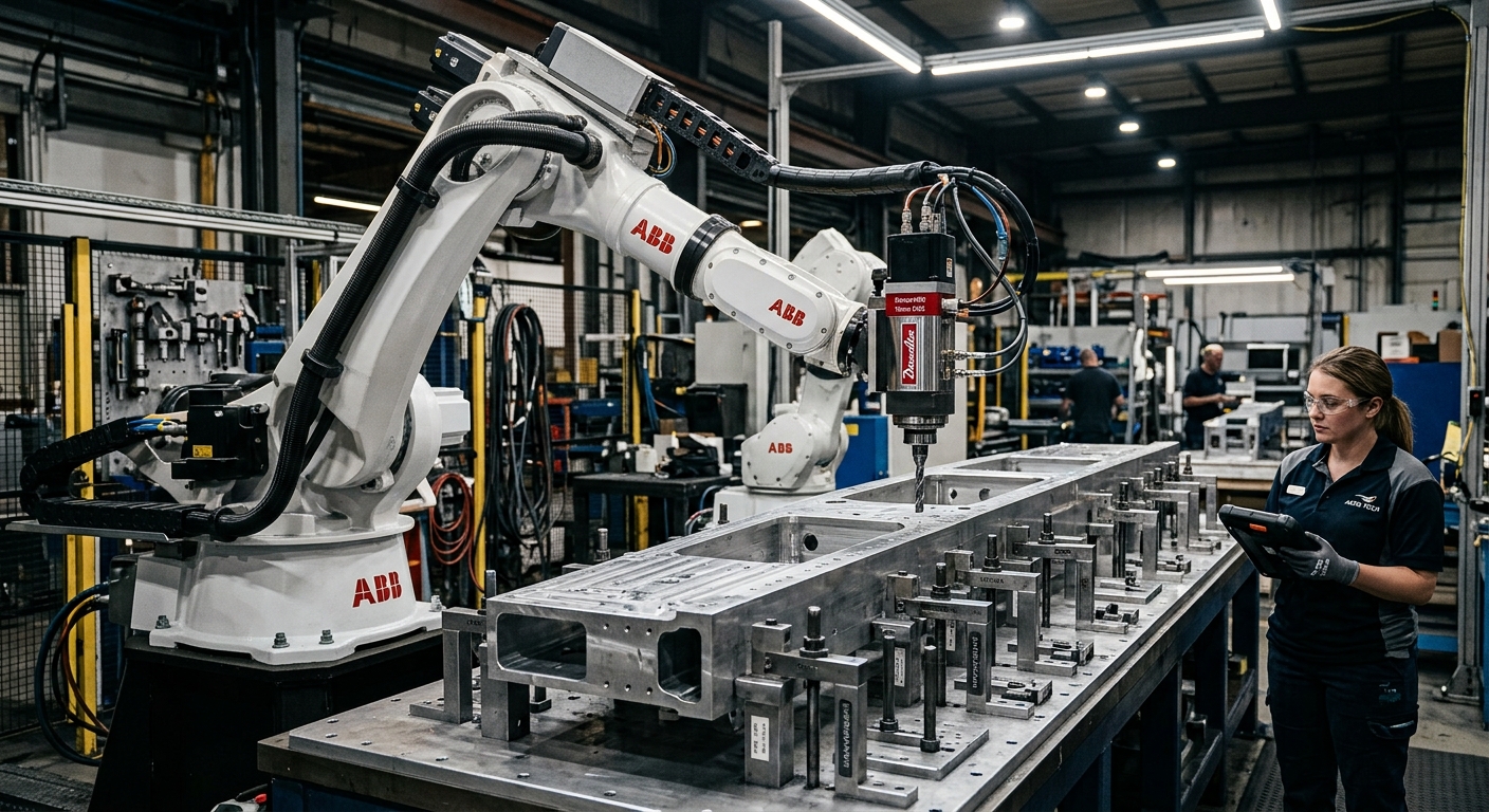

Robotic drilling accuracy in large structures depends on more than the robot’s positioning capability. Hole location is influenced by calibration, tool alignment, structural stiffness, workpiece positioning, and machining forces. When these factors are not controlled, a robot may follow its programmed coordinates while producing holes outside the required positional tolerance.
This challenge becomes more complex when drilling aircraft structures, large metal frames, fabricated assemblies, or oversized industrial components. Their dimensions create longer measurement chains, changing support conditions and greater distances between reference points. As a result, a small positioning error in one part of the system can affect the final hole location.
For production engineers, the objective is to control the complete drilling process rather than evaluate the robot independently. This article explains the main sources of positional error, how they interact, and which measurements help determine whether a robotic drilling cell can meet specified tolerances. It also examines calibration methods, fixture requirements, drilling forces, and practical acceptance checks for large structures.
What determines robotic drilling accuracy in large structures?
Robotic drilling accuracy describes how closely a drilled hole matches its specified position relative to the part’s reference geometry. Achieving the required result depends on the combined behavior of the robot, drilling spindle, workpiece, and measurement system.
Absolute accuracy versus repeatability
Repeatability describes how consistently a robot returns to a programmed position. Absolute positioning accuracy describes how closely the actual position corresponds to its commanded coordinates. A robot may demonstrate good repeatability while consistently positioning its tool away from the intended location.
This distinction matters when hole coordinates are generated from CAD models. Repeating the same movement does not correct systematic errors caused by inaccurate robot geometry, incorrect reference frames, or calibration problems.
Understanding the complete error chain
Hole position errors can originate from robot geometry, tool calibration, fixture location, thermal effects, and deformation under drilling loads. These contributions interact and cannot always be estimated by simply adding their individual magnitudes.
Engineers should evaluate the complete process using representative drilling positions. The principles discussed in the article on robotic machining repeatability also apply when assessing positional consistency across large workpieces.
How robot calibration affects hole position
Geometric calibration and coordinate systems
Industrial robots calculate tool positions using kinematic models that describe their joints and mechanical geometry. Differences between the model and actual mechanism can produce positioning errors, particularly when the robot changes configuration.
Geometric calibration identifies relevant deviations and adjusts the model where the controller supports this capability. However, calibration results must be verified across the working area used for production.
Tool center point calibration
The tool center point, or TCP, defines the working reference of the drilling tool. Incorrect TCP coordinates can cause the actual drill axis or reference point to deviate from the programmed position.
Tool orientation also requires attention. When the spindle rotates into different drilling orientations, TCP errors may become more apparent. Engineers should verify tool length, spindle alignment, and the relationship between the drill axis and robot flange.
Why structural stiffness matters during drilling
Robot deflection under machining forces
Robotic drilling accuracy depends partly on how the robot responds to machining forces. Drilling generates axial thrust and torque that act on the tool and robot structure. These loads can produce elastic deflection, particularly when the robot operates with extended joints or less favorable configurations.
Deflection can change the actual tool position and orientation during contact. Its influence depends on robot configuration, structural stiffness, tool geometry, and cutting conditions. The programmed position alone cannot describe this behavior.
Foundation and mounting stability
The robot’s mounting structure must resist forces generated during movement and machining. Flexible pedestals, poorly supported foundations, or inadequate mechanical connections can introduce additional displacement.
The technical guide on robot foundation stiffness explains how mounting conditions influence robotic performance. For drilling cells, these conditions should be evaluated before commissioning and checked when mechanical changes occur.
How fixtures and workpiece geometry influence accuracy
Large structures require stable and repeatable reference locations. Fixtures must support the component without introducing unacceptable deformation, particularly around drilling positions where material thickness and stiffness may vary.
Excessive clamping force can distort thin sections, while insufficient support may allow movement during drilling. Fixture design should therefore consider the workpiece’s geometry, material characteristics, and expected drilling loads.
Production teams should also distinguish between fixture repeatability and part geometry variation. If components arrive with different shapes or dimensions, locating them against the same supports may not establish identical drilling coordinates.
How drilling tools and cutting conditions affect hole location
Drill geometry, tool condition, and spindle alignment influence how the cutting edge enters the material. An incorrectly aligned spindle or unstable tool can introduce lateral forces that affect the hole’s starting position.
Tool runout describes radial deviation during rotation. Excessive runout can produce uneven cutting loads and affect hole geometry. The article on spindle runout in robotic milling provides related guidance on evaluating rotating tools and their mechanical connections.
Feed rate, spindle speed, and tool selection should match the material and drilling application. Pilot holes, guide bushings, or dedicated drilling units may improve process control where justified by the required tolerance and component design.
How measurement systems improve drilling accuracy
Referencing large structures
Large components may require local measurements to establish their actual position relative to the robot. Laser trackers, probing systems, and other suitable metrology equipment can support coordinate alignment when properly selected and calibrated.
The measurement strategy should use stable reference features distributed across the structure. Local alignment can help address placement variation, but it cannot automatically correct deformation or every source of machining error.
Verifying hole coordinates
Verifying robotic drilling accuracy requires comparing measured hole centers with their nominal locations using the specified datum reference frame. Coordinate measuring systems, portable metrology equipment, or suitable inspection gauges may be used according to the workpiece and tolerance requirements.
Measurements should distinguish position error from hole diameter, circularity, and orientation errors. These characteristics describe different aspects of drilling quality and may require separate acceptance criteria.
Eight checks before approving a robotic drilling cell
Before releasing a cell for production, engineers should document the accuracy requirements and verify performance under representative operating conditions. The following checks provide a practical evaluation sequence.
- Define positional tolerances: Identify the required hole position tolerance, datum references, and inspection method from the engineering drawing.
- Validate robot calibration: Compare commanded and measured positions across the working configurations used for drilling.
- Verify TCP alignment: Confirm the drilling reference point, tool length, and spindle-axis orientation after tool installation.
- Inspect mounting stiffness: Evaluate the robot base, pedestal, anchoring, and structural response under representative operating loads.
- Check fixture repeatability: Measure whether the workpiece returns to its intended location after unloading and reloading.
- Evaluate tool condition: Inspect drill geometry, tool holding, and spindle runout, and wear before representative production trials.
- Measure trial holes: Drill test features at different positions and robot configurations, then compare measured coordinates with nominal values.
- Document acceptance results: Record measurement uncertainty, operating conditions, observed deviations, and corrective actions before production release.
How to maintain accuracy during production
Robotic drilling accuracy can change as tools wear, fixtures shift, or mechanical components experience different operating conditions. Consequently, initial commissioning results should not be treated as permanent evidence of process capability.
To maintain robotic drilling accuracy, production teams should establish inspection intervals based on tolerance requirements, process behavior, and documented performance. Reference holes or representative production features can provide useful evidence of changes between scheduled inspections.
Maintenance activities should include checks of tool calibration, fixture condition, and mechanical connections. Changes to robot mounting, spindle equipment, or workpiece supports may require renewed verification before drilling resumes.
Safety also needs consideration during drilling and inspection. The OSHA guidance on industrial robot system safety addresses risk assessment, safeguarding, and the integration of robotic equipment. Safety validation remains separate from dimensional acceptance, although both are necessary before production release.
For projects involving oversized components, Robotic Hi-Tech Solutions can review drilling requirements, robot configurations, tooling, and measurement strategies. Engineering teams can contact Robotic Hi-Tech Solutions to discuss the technical requirements of a proposed drilling application.
FAQ
What is the main factor affecting robotic drilling accuracy?
No single factor determines the result. Robot calibration, structural stiffness, tooling, workpiece location, and drilling forces all influence hole position. Their relative importance depends on the application.
Can an industrial robot achieve precise hole positioning?
Yes, when the complete system meets the specified tolerance. Performance must be demonstrated through measurements under representative operating conditions rather than assumed from robot specifications.
Does robot repeatability guarantee accurate drilling?
No. Repeatability measures positional consistency, while accuracy concerns deviation from the commanded or nominal position. A repeatable robot can still produce systematically misplaced holes.
Why does drilling accuracy change across large structures?
Different robot configurations, tool orientations, fixture conditions and local workpiece stiffness can affect positioning. Errors may therefore vary across the working area.
Can laser measurement systems correct drilling errors?
They can support alignment, calibration and verification. Their effectiveness depends on measurement uncertainty, integration methods and the specific error sources being addressed.
How does drill wear influence hole position?
Uneven wear can change cutting forces and entry behavior. Depending on the tool and material, this may affect hole location, diameter or surface quality.
When should a robotic drilling system be recalibrated?
Recalibration should be considered after relevant mechanical changes, tool replacement or detected positional deviations. The required interval depends on process stability and manufacturer guidance.
How should hole position accuracy be verified?
Measure representative drilled holes against the specified datum system. Include different drilling locations, tool orientations, and operating conditions, and account for measurement uncertainty when assessing compliance.