English
 Italiano
 Українська
 Русский
 Español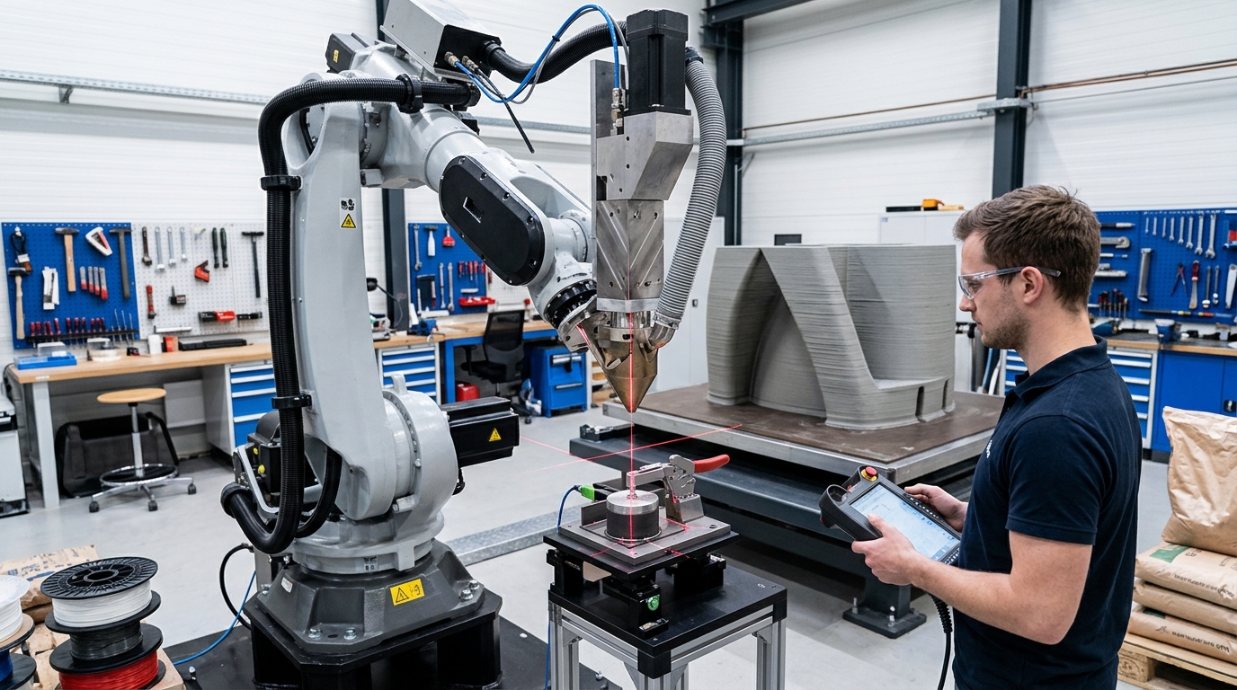

Extruder TCP calibration directly affects where a robotic 3D-printing system believes the nozzle is located and how that nozzle is oriented relative to the programmed path. If the Tool Center Point is defined incorrectly, the robot can execute the programmed motion correctly while the real extrusion point is displaced from the intended position.
This matters because robotic additive manufacturing coordinates robot motion with material deposition. An error at the TCP can therefore appear as shifted bead placement, inconsistent transitions, poor alignment between paths, or unexpected nozzle orientation. The effect becomes particularly noticeable when the robot changes orientation or follows multi-axis geometry rather than remaining in a simple planar printing position.
This article explains what the TCP represents, how calibration errors affect deposition accuracy, how to distinguish TCP problems from other process variables, and what should be checked before production. Correct calibration does not guarantee print quality by itself. Material flow, path planning, mechanical condition, thermal behavior, robot accuracy, and process control must also be considered.
What Is Extruder TCP Calibration?
The Tool Center Point, or TCP, is the reference point the robot controller uses to describe the working point of an end-effector. In robotic 3D printing, that point is normally associated with the location where material leaves the extrusion tool.
TCP position
The controller needs the TCP position relative to the robot flange or tool coordinate system. This typically involves defining offsets along the relevant coordinate axes. Those values allow the controller to calculate where the actual deposition point will be as each robot joint moves.
TCP orientation
Position alone is not sufficient for many robotic printing applications. Tool orientation determines the direction in which the extrusion head is presented to the workpiece. A positional definition can therefore appear acceptable during one pose but produce larger errors when the robot rotates the tool around complex geometry.
Why Extruder TCP Calibration Affects Printing Accuracy
Extruder TCP calibration connects the programmed trajectory to the physical nozzle. When that relationship is inaccurate, a path generated correctly in CAD, slicing, CAM, or robotic programming software can still be deposited in the wrong physical location.
Imagine that the defined TCP is slightly offset from the real nozzle tip. During a straight movement with little tool rotation, the displacement may appear relatively consistent. When the robot changes orientation, however, the incorrect offset rotates with the tool. The resulting path error can change direction and magnitude throughout the movement.
This is one reason TCP errors can be difficult to diagnose from a finished print alone. A defect may look like a path-planning problem even though the programmed path itself is correct.
How TCP Errors Appear in a Printed Part
Errors in extruder TCP calibration do not produce one universal defect. Their visible effect depends on the tool geometry, robot pose, trajectory, material, extrusion process, and how far the real TCP differs from the calibrated value.
Typical symptoms to investigate
Possible indicators include paths that meet correctly in the digital model but are displaced physically, visible offsets when the tool approaches the same point from different orientations, inaccurate starts or stops, and changes in nozzle-to-surface relationship during multi-axis deposition.
The strongest diagnostic clue is repeatable geometric behavior linked to tool orientation. If an error changes when the extruder orientation changes, the tool definition deserves examination. If the defect instead follows changes in material temperature, flow, speed, or bead dimensions, the cause may be process-related rather than geometric.
For broader context on how a robot, extruder, material supply, software, and motion strategy interact, the RHTS article on FANUC and Leister robotic 3D printing describes an application in which robotic movement and extrusion must be coordinated as one system.
What Else Can Be Mistaken for a TCP Problem?
Not every dimensional or deposition error is caused by extruder TCP calibration. Troubleshooting should separate the robot’s geometric tool definition from the variables that influence the material after it leaves the nozzle.
Extrusion rate, travel speed, material temperature, bead geometry, material consistency, nozzle condition, and start-stop behavior can all influence the shape of a deposited path. A mechanically loose extruder mount can also create movement that a perfect TCP definition cannot correct.
Robot calibration and TCP calibration should not be treated as identical either. TCP calibration defines the tool relative to the robot. Robot geometric accuracy depends on the robot itself and its kinematic model. A correctly defined extrusion tool cannot compensate automatically for unrelated errors elsewhere in the robotic system.
How to Verify the Extruder TCP Before Printing
A useful extruder TCP calibration verification procedure should test whether the physical nozzle reaches a common reference consistently from different robot poses. The exact calibration procedure varies with the robot manufacturer, controller, tool geometry, available measurement equipment, and required process accuracy.
Use multiple tool orientations
Checking the nozzle from only one orientation is insufficient for identifying many TCP errors. The robot should approach the chosen reference through multiple suitable orientations while the operator observes whether the same physical point is maintained. A changing point of contact or alignment can indicate an incorrect tool definition or another mechanical problem.
The mounting arrangement should also be inspected before adjusting software values. If the extruder, nozzle, adapter, or flange connection can move mechanically, recalibrating the TCP may only compensate temporarily for an unstable tool.
Eight Checks for Reliable Extruder TCP Calibration
The following checks help separate geometric calibration issues from extrusion and mechanical problems before a printing program is validated:
- Confirm the physical reference point. Define precisely which location on the extrusion system represents the TCP, normally the intended deposition point at or near the nozzle outlet.
- Inspect the extruder mounting. Check that the tool, flange adapter, brackets, and nozzle are securely installed before taking calibration measurements.
- Verify the active tool data. Confirm that the robot program is using the intended tool definition rather than another TCP stored in the controller.
- Test several orientations. Approach a suitable reference from different robot poses to expose errors that may remain hidden in a single orientation.
- Check after nozzle changes. Determine whether replacing, removing, or repositioning the nozzle changes the physical deposition point relative to the stored tool data.
- Separate geometry from material flow. Perform geometric checks independently from bead-width, temperature, extrusion-rate, and material-quality adjustments.
- Validate with a controlled print. Use a simple test geometry whose path placement and orientation changes make deviations easier to observe than on a complex production part.
- Record the accepted configuration. Document the tool assembly, nozzle configuration, TCP data, and calibration condition so later changes can be compared with a known setup.
When Should Extruder TCP Calibration Be Rechecked?
Extruder TCP calibration should be reviewed whenever the physical relationship between the robot flange and deposition point may have changed. The appropriate verification interval depends on the specific equipment, process, maintenance procedures, and required accuracy rather than on one universal schedule.
Changes that can justify recalibration
Examples include removing or reinstalling the extruder, replacing a nozzle with one that changes the effective tool geometry, modifying a tool adapter, repairing the extrusion head, or detecting unexpected path displacement after maintenance or a mechanical event.
A tool change does not necessarily mean that every parameter must be rebuilt from zero. What matters is whether the location or orientation of the real deposition point has changed relative to the stored tool definition. Verification provides evidence before production resumes.
The broader principles of robotic additive manufacturing and the role of a multi-axis extrusion head are also discussed in RHTS’s overview of 3D printing with a robotic arm.
TCP Calibration Must Be Considered With the Complete Cell
Accurate tool data is only one part of commissioning a robotic printing cell. Robot base definition, work-object coordinates, external axes, path generation, material delivery, extrusion commands, mounting stiffness, and process parameters all contribute to the relationship between the digital trajectory and deposited material.
Safety requirements must also be addressed independently from geometric calibration. An accurate TCP does not make a robotic cell safe. Industrial robot applications require risk assessment and appropriate protective measures for the integrated system, including hazards created by the particular application. The ISO 10218-2 standard for industrial robot applications and robot cells addresses requirements related to robot integration and the lifecycle of industrial robot applications.
Teams evaluating a robotic extrusion system can contact Robotic Hi-Tech Solutions to discuss the robot, extruder configuration, application geometry, integration requirements, and calibration considerations for a specific project.
FAQ
What does TCP mean in robotic 3D printing?
TCP means Tool Center Point. It is the reference point used by the robot controller to represent the working location of the extrusion tool relative to the robot.
Can an incorrect TCP cause dimensional errors?
Yes. If the real deposition point does not match the TCP stored in the controller, the physical extrusion path can be displaced from the programmed trajectory.
Why can TCP errors become worse when the extruder rotates?
An incorrect positional offset rotates with the tool. As orientation changes, the resulting displacement can therefore change direction and become more visible.
Is TCP calibration the same as robot calibration?
No. TCP calibration defines the end-effector relative to the robot. Robot calibration concerns the robot’s geometric or kinematic accuracy. They affect different parts of the positioning chain.
Should the TCP be checked after replacing a nozzle?
It should be verified when the replacement could alter the location or orientation of the effective deposition point. Identical components may still warrant a check when process accuracy is sensitive to tool geometry.
Can TCP calibration correct extrusion-flow problems?
No. TCP calibration corrects the geometric definition of the tool. Flow instability, temperature problems, material inconsistency, and extrusion-rate errors require separate process troubleshooting.
How can a TCP error be distinguished from a path-programming error?
Testing the same physical reference from several tool orientations helps isolate the tool definition. If the programmed point is constant but the real nozzle position changes with orientation, the TCP or mechanical tool setup should be examined.
Does accurate extruder TCP calibration guarantee print accuracy?
No. It removes one potential source of geometric error. Final accuracy also depends on robot performance, coordinate-system setup, tool rigidity, path planning, extrusion control, material behavior, and the requirements of the specific printed part.