
Why Dimensional Stability Is the Real Test in Large-Format Robotic Milling
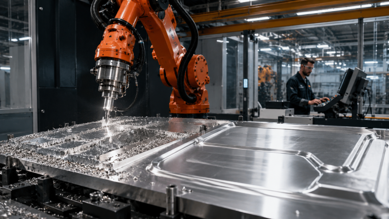
Robotic Milling Stability is the real test in large-format robotic milling. The question is rarely whether the robot can reach the part. The harder question is whether Robotic Milling Stability can be maintained across the full work envelope, through changing tool loads, long cycle times, fixture variation, and measurement feedback.
Large-format parts expose every weakness in the cell. A small calibration error, a fixture that moves under load, a spindle package with insufficient stiffness, or a toolpath that changes cutting force direction can create dimensional drift that is not visible during a short demonstration cut.
This is why robotic milling should not be evaluated as a simple substitute for a CNC machine. It can be a strong option for trimming, finishing, foam, composites, plastics, patterns, molds, and certain low-force machining operations. It becomes risky when the buyer expects CNC-style rigidity without designing the cell around the limits of the robot, spindle, fixture, tooling, and measurement process.
Robotic Milling Stability should be evaluated as a complete system condition, not only as a robot specification.
When Robotic Milling Is Suitable for Large-Format Parts
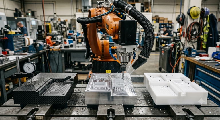
Robotic milling is most suitable when the production problem is defined by access, envelope size, part handling, or flexibility rather than heavy material removal. A robot can move around a large part more easily than a fixed machine tool in many layouts, especially when the part is too large, awkward, or expensive to move repeatedly between stations.
The application becomes more realistic when the material and cutting strategy allow controlled forces. Trimming composite parts, machining foam patterns, finishing plastics, removing flash, cutting light alloys under controlled conditions, or preparing surfaces can fit robotic milling when the required tolerance matches what the full cell can hold.
The cell should be evaluated against the actual production requirement, not the theoretical capability of the robot arm. The relevant question is whether the robot, spindle, tool, fixture, calibration method, program, and inspection plan can produce the required geometry repeatedly under production conditions.
For large-format parts, Robotic Milling Stability becomes critical because small reference errors can grow across the full work envelope.
For a broader application overview, Robotic-Hitechsolutions article on REFURBISHED ROBOTS IN LARGE-SCALE 3D PRINTING: ARCHITECTURE, MOLDS, AND FUNCTIONAL ART is a useful companion to this dimensional stability discussion.
A large envelope does not mean stable accuracy
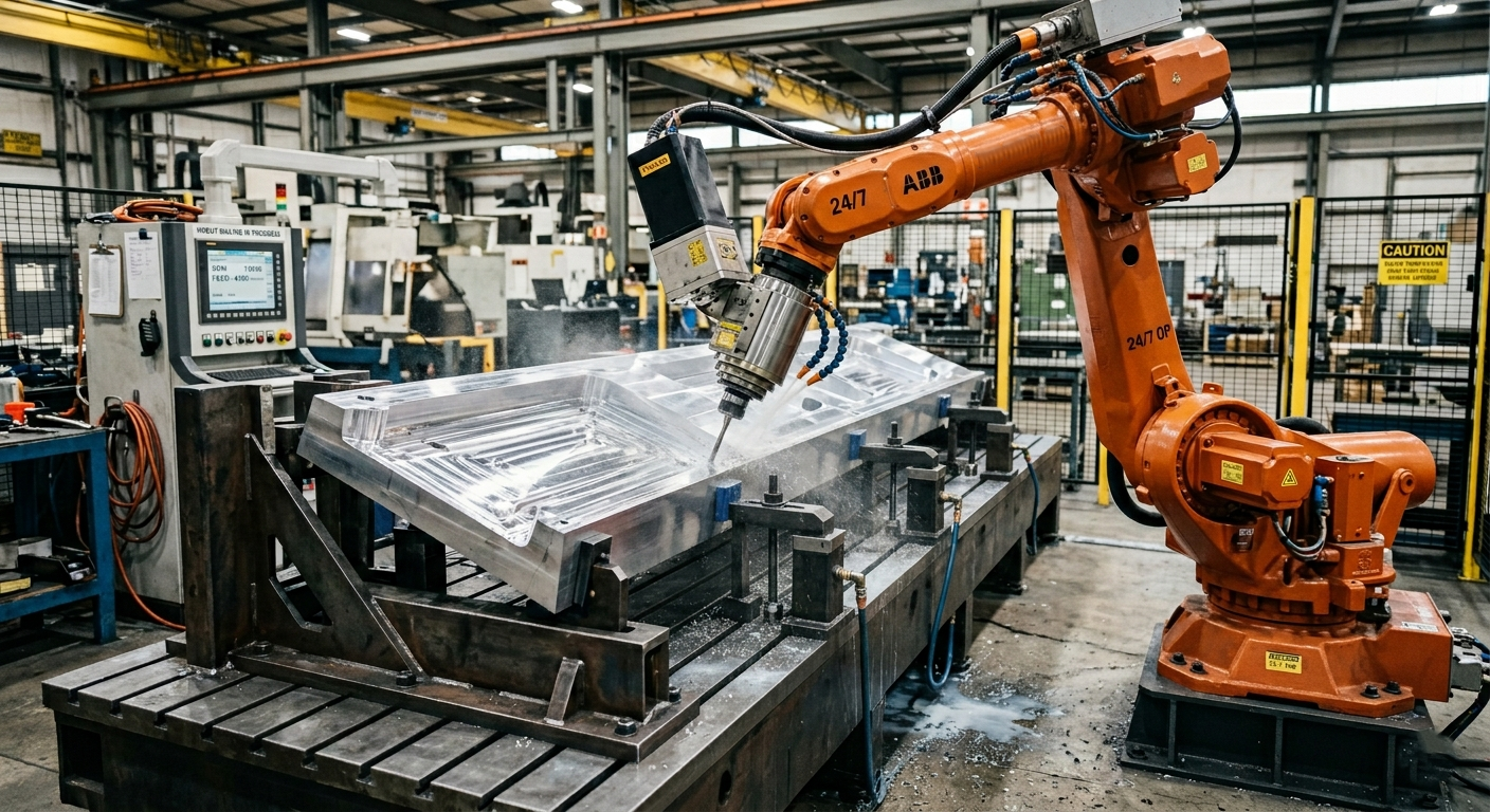
A large robot can cover a wide area, but dimensional stability depends on how the robot behaves at each position and orientation. The arm may be more rigid in one posture than another. The spindle may load the wrist differently depending on the tool direction. The fixture may support the part well in one zone and poorly in another.
For large-format parts, this means the cell must be validated across the complete machining area. A successful test on one corner of the part does not prove that the opposite side, a deep feature, or a long edge cut will hold the same result.
Material behavior matters as much as robot behavior
Large parts often move, relax, or vibrate during machining. Composite parts can have residual stress. Plastic parts can deform with heat. Foam can compress. Thin shells can shift if the vacuum support or mechanical clamping is uneven.
If the part moves while the robot repeats the same path, the robot may appear to be the problem even when the root cause is part support. Dimensional stability has to be treated as a system issue, not only a robot accuracy issue.
The Process Conditions That Must Be Stable Before Milling Starts
Robotic milling is sensitive to variation before the spindle ever touches the part. Part location, fixture repeatability, temperature, tool condition, spindle runout, calibration, and program origin all affect whether the machined geometry matches the intended geometry.
The first process check is part presentation. Large-format parts must be located in a way that is repeatable enough for the required tolerance. If the part is manually placed with inconsistent datum contact, the robot will reproduce a path relative to a reference that may not match the real part position.
The second check is fixture stiffness. A fixture that is acceptable for assembly, inspection, or manual finishing may not be acceptable for robotic milling. Cutting force, vibration, vacuum loss, clamp movement, and thermal expansion can all change the part position during the cycle.
The third check is the datum strategy. The cell needs a clear method for relating the robot program to the part. This may involve mechanical datums, probing, vision, laser tracking, external measurement, or a combination of methods. The method should be chosen based on tolerance requirement, part size, material, and cycle time impact.
Milling is a subtractive machining process where a rotating cutting tool removes material from a workpiece, making process control essential for robotic applications. For a broader technical explanation, see this external guide on what milling is in machining.
Repeatability is not the same as dimensional accuracy
A robot can repeat a motion consistently and still produce a wrong feature if the tool center point, base frame, work object, fixture, or part model is incorrect. Repeatability tells you whether the robot can return to a taught or programmed position. It does not prove that the position is dimensionally correct relative to the real part.
This distinction is critical in large-format milling. The larger the part, the more small reference errors can accumulate into a visible mismatch at the far end of the work envelope.
Thermal and time effects should not be ignored
Long milling cycles can introduce dimensional drift through heat in the spindle, tool, part, fixture, or surrounding environment. Even if each individual effect is small, the combination can matter when the part is large, and the tolerance window is tight.
The practical response is not to assume the cell is unstable. The practical response is to measure whether the process changes over the full cycle, then decide whether warm-up routines, intermediate measurement, tool compensation, environmental control, or fixture changes are needed.
Technical Requirements for Robotic Milling Stability
Robotic Milling Stability depends on controlled force, controlled reference, and controlled feedback. The robot arm is only one part of that system. The spindle, toolholder, cutter, fixture, measurement method, robot program, safety system, and operator procedure all influence the final part.
The spindle package must be selected for the process, not only for nominal power. Weight, center of gravity, mounting stiffness, cooling, cable routing, dust extraction, and tool change strategy all affect cell behavior. A heavy or poorly balanced spindle can reduce useful performance because it loads the robot’s wrist and changes dynamic behavior.
Tooling must also be chosen conservatively. Tool length, cutter geometry, engagement, feed strategy, and tool wear affect cutting force. Long tools may be necessary for access, but they can increase deflection and vibration. Aggressive cutting parameters may reduce cycle time on paper while increasing scrap risk in production.
Programming is another major stability factor. Offline programming can reduce programming time, especially for large parts and complex paths, but it depends on accurate cell models, calibrated frames, and verified tool data. Parametric Design and Robotics: The New Era of Creative Fabrication
Calibration must be treated as a production process
Calibration is not a one-time commissioning task for large-format milling. Robot base calibration, tool center point calibration, spindle alignment, fixture location, and part datum verification should be controlled as part of the production method.
If the cell relies on manual checks that vary by operator, dimensional stability becomes dependent on habits rather than process control. The better approach is to define what must be checked, how often it must be checked, and what action is taken when the measurement is outside the allowed window.
Accurate calibration protects Robotic Milling Stability by keeping the robot, tool, fixture, and part reference aligned.
Measurement feedback should match the tolerance risk
Not every robotic milling cell needs advanced metrology, but large-format parts often require some form of verification beyond visual inspection. The inspection method may be simple for rough trimming and more demanding for features that must align with downstream assembly.
Machine vision, probing, laser measurement, or external inspection can help when the measurement plan is connected to real correction logic. INDUSTRIAL ROBOTS IN ART: CREATIVITY, PRECISION, AND ACCESSIBLE TECHNOLOGY WITH RETROFITTED ROBOTICS
Where Dimensional Error Usually Enters the Cell
Dimensional error in robotic milling usually comes from several small sources rather than one obvious failure. The robot may be repeating correctly, while the part is slightly misplaced, the tool is wearing, the fixture is flexing, or the program frame is not aligned with the physical setup.
The most common mistake is to blame the robot arm before separating the sources of error. A practical investigation should distinguish between robot motion error, tool deflection, spindle behavior, fixture movement, part movement, program error, and measurement error.
This is especially important when the cell produces acceptable parts at the beginning of a run and unstable results later. That pattern may point to tool wear, heat, fixture movement, dust accumulation, vacuum loss, or a process variable that changes over time.
The table below gives a practical way to think about common dimensional stability risks before investing in a large-format robotic milling cell.
| Risk area | What can go wrong | What to verify before production |
|---|---|---|
| Part location | The robot mills the correct path relative to the wrong part position. | Datum repeatability, loading method, clamping sequence, and part detection. |
| Fixture stiffness | The part moves under cutting force or changes position during the cycle. | Support points, vacuum stability, clamp force, vibration, and access clearance. |
| Tooling | Tool deflection or wear changes the actual cut path. | Tool length, cutter geometry, wear monitoring, and replacement criteria. |
| Spindle package | Weight, balance, runout, or mounting stiffness affects milling behavior. | Spindle integration, bracket stiffness, cable routing, and tool center point control. |
| Calibration | Robot, tool, fixture, and part references do not match the real cell. | Base frame, TCP, work object, fixture model, and verification procedure. |
| Program strategy | Path direction or engagement creates variable force across the part. | Approach paths, stepovers, feeds, cutter engagement, and posture changes. |
| Inspection | Dimensional drift is found too late or measured inconsistently. | Measurement method, inspection frequency, acceptance criteria, and correction loop. |
Where ROI Usually Comes From in Large-Format Robotic Milling
For large-format applications, Robotic Milling Stability directly affects ROI because dimensional drift can increase rework, scrap, inspection time, and manual correction.
A robot may be attractive when a dedicated large CNC machine is too expensive, too constrained by envelope, or not justified by production volume. However, that does not mean the robot is automatically the lower-cost option. The real comparison must include spindle integration, fixturing, programming, metrology, dust extraction, safety, commissioning, operator training, and ongoing maintenance.
For dimensional stability, the ROI calculation should include the cost of poor quality. If unstable milling creates rework, scrap, delayed assembly, manual correction, or customer rejection, the lowest purchase price can become the most expensive option. A stable process may justify more investment in fixture design, measurement, or programming because those elements protect the output.
Cycle time must be evaluated with quality included
A faster cut is not a better cut if it increases deflection, vibration, or inspection failures. The correct cycle time target is the fastest repeatable cycle that holds the required geometry under production conditions.
This is why acceptance testing should include more than a successful first article. It should include repeated parts, tool wear behavior, warm cell conditions, operator loading variation, and inspection data across the areas of the part that are most sensitive to error.
Flexibility has value only when changeover is controlled
Robotic milling can support multiple large part variants when the cell is designed for controlled changeover. That may require fixture recipes, verified programs, tool data management, part identification, and clear operator instructions.
If each changeover depends on manual adjustment and informal judgment, flexibility becomes a source of instability. The business case should include the time and risk associated with switching between parts, not only the number of variants the robot can theoretically process.
Common Mistakes When Automating Large-Format Milling
The first mistake is evaluating reach before stiffness. Reach matters, but a robot that can physically access the full part may still be unsuitable if the posture, spindle load, or cutting direction creates unacceptable deflection.
The second mistake is treating the fixture as a secondary item. In large-format milling, the fixture is often the difference between a stable cell and a cell that produces variable results. The fixture must locate, support, and hold the part in the condition in which it will be machined.
The third mistake is underestimating calibration and inspection. Large parts make small errors visible. If the cell has no disciplined method for checking references and verifying results, the plant may not know whether the problem is programming, loading, tooling, robot behavior, or measurement.
The fourth mistake is automating a process that is not yet controlled manually. If operators currently compensate for inconsistent parts, unclear datums, unstable trimming lines, or fixture movement, the robot will not remove those problems. It will repeat them more consistently.
ART, ARCHITECTURE, AND ROBOTICS: WHEN THE ARM BECOMES THE AUTHOR
Safety and access are part of stability
Large-format milling cells require safe access for loading, unloading, inspection, tool changes, dust management, and maintenance. If operators need frequent intervention in awkward locations, the cell design may create downtime and safety risk.
When Robotic Milling Should Not Be Automated Yet
Robotic milling should be delayed if the required tolerance is tighter than the cell can verify and maintain. The decision should be based on the complete process capability, not on a demonstration, a robot brochure, or a single successful trial cut.
The application may also be unsuitable if the material requires high cutting forces that exceed the practical stiffness of the robot-spindle-fixture system. In those cases, a CNC machine, gantry system, hybrid approach, or redesigned process may be safer.
Automation should also be delayed when the part has no stable datum strategy. If each part arrives differently and the plant has no reliable way to locate it, the robot program will depend on assumptions that may not match production reality.
Finally, robotic milling may not be ready if the plant cannot support the cell after commissioning. Spindle maintenance, tool management, calibration checks, dust extraction, safety validation, and troubleshooting require ownership. Without that ownership, dimensional stability can degrade after the integrator leaves.
What to Check Before Investing in Robotic Milling for Large Parts
The checklist below is intended for early technical screening. It should be used before selecting a robot model, spindle, or integrator proposal, because the answers affect the entire cell design.
- Define the tolerance requirement: Separate rough trimming, finishing, drilling, edge preparation, and critical features instead of treating the whole part as one tolerance problem.
- Map the full work envelope: Check the most difficult robot postures, not only the easiest area of the part.
- Verify part support: Confirm that the fixture holds the part in the same condition during loading, cutting, inspection, and unloading.
- Control the datum strategy: Decide how the robot program will be aligned to the real part every time.
- Evaluate spindle integration: Review weight, center of gravity, mounting stiffness, cooling, cable routing, dust extraction, and tool change requirements.
- Test cutting forces: Validate tool engagement, feed strategy, tool length, vibration, and surface quality under realistic conditions.
- Plan inspection: Define what will be measured, when it will be measured, and what correction is allowed before production continues.
- Include maintenance ownership: Assign responsibility for calibration checks, tool management, spindle care, safety checks, and troubleshooting.
- Validate repeated production: Do not approve the cell only on the first article. Test repeated parts, warm-up behavior, operator loading variation, and tool wear.
If the project involves a used or refurbished robot, the buying decision should also include mechanical condition, controller version, service history when available, spare parts, software options, and compatibility with the spindle and measurement system.
In summary, Robotic Milling Stability depends on the complete cell: robot, spindle, fixture, tooling, calibration, programming, and measurement.
FAQ
Can robotic milling hold tight tolerances on large-format parts?
It can hold useful production tolerances when the requirement matches the complete cell capability. The result depends on robot posture, spindle stiffness, tool deflection, fixture support, calibration, part behavior, and inspection feedback. It should not be assumed from robot repeatability alone.
Is robotic milling a direct replacement for a CNC machine?
Not in every case. Robotic milling can be attractive for large envelopes, trimming, finishing, and flexible processing, but CNC machines usually provide higher structural rigidity for demanding metal cutting. The right choice depends on material, tolerance, cutting force, part size, volume, and total project cost.
What causes dimensional drift in robotic milling?
Dimensional drift can come from tool wear, heat, fixture movement, part movement, calibration error, spindle behavior, dust accumulation, or inconsistent loading. The robot may be repeating correctly while another part of the process changes during the cycle.
How important is fixturing for large-format robotic milling?
Fixturing is critical. A fixture must locate and support the part in the condition required for machining. If the part moves, vibrates, relaxes, or is loaded inconsistently, the robot path may be repeatable but the finished geometry will still vary.
A rigid and repeatable fixture is one of the most important requirements for Robotic Milling Stability.
Should measurement be integrated into the robotic milling cell?
Measurement should be integrated when the tolerance risk justifies it. Some applications may only need periodic inspection, while others require probing, vision, laser measurement, or external metrology. The key is that measurement must lead to a defined decision, such as correction, tool change, rework, or rejection.
Can a used industrial robot be suitable for robotic milling?
Yes, but only if its mechanical condition, controller capability, payload margin, reach, stiffness behavior, software options, and integration compatibility fit the milling application. The lower purchase price is not enough if the robot cannot support the spindle, calibration method, safety system, and production tolerance.
What should be tested before approving a robotic milling project?
The project should be tested with representative parts, real fixtures, intended tooling, realistic cutting parameters, repeated cycles, and the planned inspection method. A short demonstration cut is not enough to prove dimensional stability for large-format production.
Talk to Robotic-HiTech Solutions About Robotic Milling Stability
Need better Robotic Milling Stability for large-format parts? Contact Robotic-HiTech Solutions to evaluate your fixture, spindle, tooling, calibration strategy, inspection workflow, and robotic milling process.