English
 Italiano
 Українська
 Русский
 Español
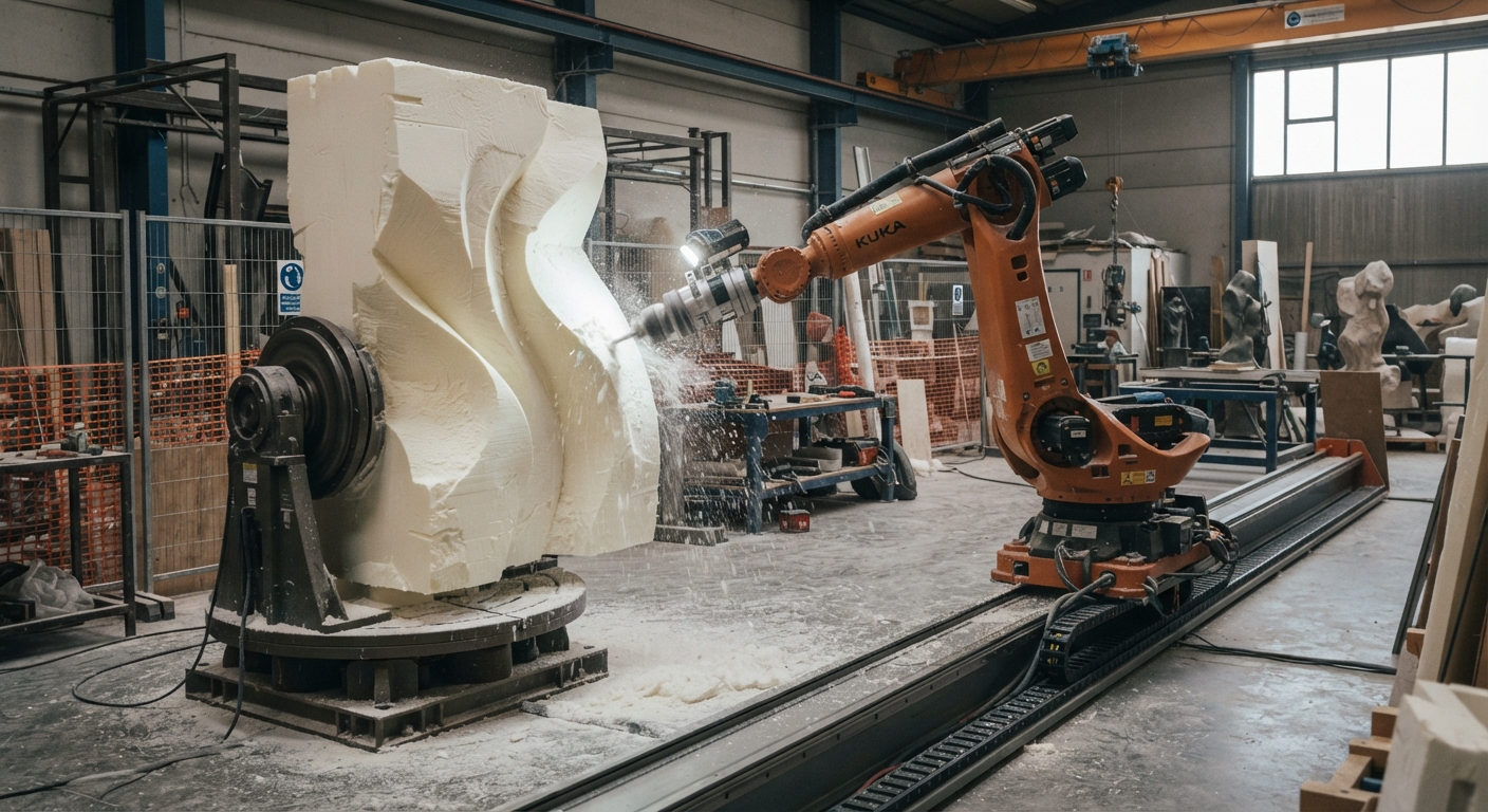

External axes expand the scale of robotic sculpture by allowing industrial robots to move beyond their fixed working envelope. A six-axis robot can carve complex surfaces, but its reach limits the size and position of the workpiece. Adding a linear track or rotary positioner changes how the robot accesses large sculptural forms without necessarily requiring a larger robotic arm.
In large-scale fabrication, external axes provide additional movement between the robot, its cutting tool, and the material. A linear track moves the robot along an extended working area. A rotary positioner turns the sculpture so the tool can approach different surfaces. These arrangements can support larger components, reduce manual repositioning, and improve access to complex geometry.
However, additional movement does not automatically improve machining accuracy or eliminate manufacturing constraints. Engineers must evaluate mechanical stiffness, coordinated motion, calibration, and safety. This article explains how external axes work, when they are useful, and what fabrication teams should verify before integrating them into robotic sculpture production.
1. How external axes change robotic sculpture fabrication
A conventional industrial robot operates within a defined working envelope. Its joints determine which positions and tool orientations it can reach. Large sculptures may extend beyond that envelope, leaving surfaces inaccessible even when the robot has enough payload capacity for the cutting tool.
Extending the robot’s working envelope
External axes add controlled movement outside the robot’s standard joints. Depending on the configuration, they can move the robot itself or reposition the workpiece. This expands the range of accessible machining positions without changing the robot’s original arm geometry.
Understanding additional degrees of freedom
A six-axis robot normally controls six joint movements. An integrated external axis adds another controlled movement, although the total number of simultaneously coordinated axes depends on the controller and software. Additional axes create more positioning options but also increase programming complexity.
2. How linear tracks support larger sculptures
Linear tracks allow an industrial robot to travel along a guided rail system. Instead of working from one fixed base position, the robot can reach different sections of an elongated sculpture. This arrangement suits large panels, architectural ornaments, and extended sculptural components.
Moving the robot along the workpiece
A track-mounted robot can machine one section before moving to another. The controller may coordinate track travel with arm movement or use separate indexed positions. The chosen method depends on the application, controller capabilities, and required machining continuity.
Managing transitions between machining areas
When the robot changes track positions, the machining program must preserve the relationship between the tool and the sculpture. Incorrect calibration or inconsistent reference frames can create visible differences between adjacent areas. Engineers should verify these transitions before machining the finished material.
Linear tracks are particularly useful when the sculpture has a long horizontal dimension. However, the track structure, installation alignment, and available floor space must support the intended manufacturing process.
3. Why rotary positioners improve access to complex surfaces
Rotary positioners turn or tilt a workpiece relative to the robot. They can expose surfaces that would otherwise require difficult tool orientations or manual repositioning. This is useful for sculptures with curved backs, recessed areas, or features distributed around several sides.
Single-axis and multi-axis positioners
A single-axis positioner rotates the workpiece around one axis. Multi-axis arrangements can provide additional orientation control. Selection depends on the sculpture’s geometry, mass distribution, mounting requirements, and available robot configurations.
Coordinating rotation with tool movement
In coordinated operation, the controller accounts for workpiece movement while calculating the robot’s tool position. This can support machining around curved surfaces, provided the software and mechanical system are compatible.
Rotary systems must also withstand the workpiece load and machining forces. Engineers should verify rated capacity, center-of-gravity limits, bearing support, and fixture rigidity before approving the configuration.
4. How external axes affect machining accuracy
Adding movement increases the number of mechanical and geometric relationships that influence the finished sculpture. Track alignment, positioner accuracy, robot calibration, and tool deflection all contribute to machining performance.
Calibration and coordinate systems
The robot controller must understand the relationship between the robot base, external axis, tool center point, and workpiece reference frame. Calibration establishes these relationships so programmed movements correspond to the physical installation.
Errors can become visible where machining paths overlap or where different surfaces meet. Calibration should therefore be checked after mechanical adjustments, fixture changes, or other modifications that affect the system’s geometry.
Stiffness and machining forces
External axes introduce additional structures that may deflect under load. Rail supports, positioner frames, and mounting connections must withstand expected forces. The effect depends on the material, tool engagement, robot posture, and mechanical design.
Surface quality also depends on the machining strategy. The article on robotic toolpath resolution and sculptural surface quality explains how programmed movement affects the reproduction of curved details.
5. How coordinated motion changes programming requirements
Coordinated motion requires the robot controller to manage the relationship between the arm and external equipment. Not every robot controller supports every axis configuration, and some systems require additional software options or integration components.
Programming continuous machining paths
Continuous coordinated movement can allow the robot and external axis to move during the same machining operation. This may reduce interruptions when processing extended surfaces. However, the complete motion must remain within joint limits, axis travel limits, and collision constraints.
Simulation before physical machining
Offline simulation helps engineers examine tool access, robot posture, and potential collisions. The simulation model should include the track, positioner, fixtures, workpiece, and surrounding equipment.
Simulation cannot fully predict structural deflection or every machining effect. Physical validation remains necessary, especially when the process involves significant cutting forces or tight dimensional requirements.
6. When external axes are preferable to dividing a sculpture
Large sculptures can be manufactured as separate components or processed using an extended robotic cell. Neither approach is universally preferable. The decision depends on the geometry, material dimensions, assembly requirements, and available manufacturing space.
External axes may reduce the number of manufacturing setups when a large workpiece can remain securely mounted. However, transport restrictions or material stock dimensions may still require segmentation. The article on dividing large sculptures for robotic fabrication explains how section boundaries influence manufacturing and assembly.
For architectural projects, external axes can also improve access to long decorative panels and curved components. The design process must still account for machining clearances, installation interfaces, and the final assembly sequence.
7. What to verify before adding external axes
External axes should be selected according to the complete manufacturing task rather than maximum travel alone. The following checks help identify whether a proposed configuration can support the sculpture and its machining process.
- Workpiece dimensions: Measure the complete sculpture, including fixtures and required tool clearance.
- Robot reach: Check accessible tool positions and orientations throughout the proposed axis travel.
- Payload capacity: Verify positioner load ratings, workpiece mass, and center-of-gravity restrictions.
- Mechanical stiffness: Evaluate rail supports, mounting structures, fixtures, and expected machining forces.
- Controller compatibility: Confirm supported external axes, coordination functions, and required software options.
- Calibration requirements: Define reference frames and methods for verifying alignment across machining positions.
- Collision clearance: Simulate the robot, tooling, moving equipment, and workpiece throughout the operating range.
- Safety integration: Assess moving-axis hazards, protective measures, emergency stops, and access requirements.
The selected arrangement should be validated with representative toolpaths and material tests. These checks help identify mechanical or programming limitations before the full sculpture enters production.
8. How to integrate external axes into a robotic sculpture cell
Integration begins with the sculpture’s geometry and manufacturing process. Engineers determine whether the main limitation is longitudinal reach, workpiece orientation, or a combination of both. This determines whether a linear track, rotary positioner, or combined configuration deserves further evaluation.
Planning the complete fabrication workflow
The cell layout must accommodate material loading, fixtures, machining access, maintenance, and finished-part removal. Large workpieces may require lifting equipment and additional space around the moving axes.
For related design considerations, the article on designing architectural parts for robotic fabrication explains how geometry, tool access, and manufacturing constraints influence component preparation.
Safety and commissioning
Moving tracks and positioners introduce additional hazards, including crushing and trapping points. Risk assessment must address the complete installation, not only the robotic arm. The OSHA technical guidance on industrial robots and robot system safety provides relevant background for identifying robotic system hazards.
Commissioning should include controlled movement tests, reference-frame verification, protective-function checks, and representative machining trials. These activities help establish whether the integrated system performs as intended.
For projects involving large sculptural components, contact Robotic Hi-Tech Solutions to discuss robot configurations, external-axis integration, and the technical requirements of the proposed fabrication process.
9. Frequently asked questions
What is an external axis in industrial robotics?
An external axis is an additional controlled movement integrated with a robotic system. Common examples include linear tracks and rotary positioners. It can move the robot or reposition a workpiece to extend access beyond the robot’s fixed working envelope.
Can external axes make a robot manufacture larger sculptures?
Yes. External axes can increase the accessible manufacturing area or improve workpiece orientation. However, the maximum sculpture dimensions still depend on axis travel, mechanical capacity, tooling, fixtures, and available installation space.
Is a linear track better than a rotary positioner?
Neither is automatically better. Linear tracks are useful for extended workpieces, while rotary positioners improve access around different sides of a component. Some applications benefit from combining both systems.
Do external axes improve robotic machining accuracy?
Not automatically. They can improve access and allow more suitable machining positions, but accuracy depends on calibration, structural stiffness, controller performance, and process conditions. Additional mechanical components can introduce further error sources.
Can every industrial robot use external axes?
No. Compatibility depends on the robot controller, available software, supported axis configurations, and integration hardware. Engineers should verify the manufacturer’s documentation before selecting an external-axis system.
Can a robot and positioner move simultaneously?
Yes, when the controller and application support coordinated motion. The controller must maintain the required relationship between the tool and moving workpiece. This capability should be confirmed for the specific robot and positioner combination.
Are external axes suitable for stone and wood sculpture?
They can support both applications when the equipment is designed for the material and machining forces. Stone cutting may impose different structural and tooling demands from wood carving. Dust protection and equipment maintenance also require consideration.
When is an external axis unnecessary?
An external axis may be unnecessary when the existing robot reaches all required surfaces with suitable tool orientations. It may also be difficult to justify when simpler fixtures, workpiece repositioning, or component segmentation meet the manufacturing requirements.