English
 Italiano
 Українська
 Русский
 Español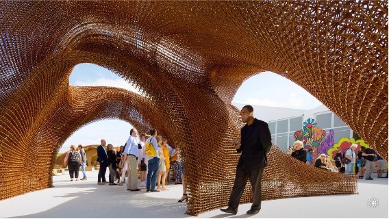

Robotic 3D printing for art and architecture uses industrial arms to deposit polymers, composites, clay, concrete, metal, and experimental materials across large or geometrically complex forms. Unlike a conventional Cartesian printer, a six-axis robot can change both the position and orientation of the deposition tool, creating fabrication strategies that are not limited to horizontal layers inside a rectangular build volume.
This additional freedom can support large sculptures, architectural panels, customised components, molds, installations, furniture, and metal structures. It does not mean the robot can print any form without support or material constraints. Every project must still account for gravity, cooling, curing, layer bonding, robot reach, nozzle access, collision risk, and structural performance.
The industrial arm provides programmable movement. The creative and technical value comes from the complete system connecting digital design, path planning, material delivery, robot simulation, calibration, deposition control, and physical validation.
Quick Answer
- Art: robotic printing can produce large sculptures, installations, furniture, and customised physical works.
- Architecture: it can fabricate panels, formwork, components, prototypes, and selected construction-scale structures.
- Six-axis movement: the nozzle can change orientation instead of remaining permanently vertical.
- Large-scale production: external tracks and positioners can expand the working envelope.
- Material freedom: different systems can deposit polymers, clay, concrete, composites, or metal.
- Technical reality: the robot arm alone is not a printer; tooling, software, process control, safety, and material engineering remain essential.
Robotic additive manufacturing becomes creatively useful when its movement capabilities serve a material and design objective that conventional printing cannot achieve efficiently.
What Robotic 3D Printing Means
Robotic 3D printing is an additive-manufacturing process in which an industrial robot moves a deposition tool through a programmed trajectory while material is added progressively to create a physical object.
The robot may carry:
- a thermoplastic pellet extruder;
- a filament or paste nozzle;
- a clay or ceramic deposition system;
- a concrete or mortar print head;
- a wire-fed welding torch;
- a directed-energy deposition head;
- a composite or fibre-placement tool;
- custom experimental material-delivery equipment.
The term covers several technically different processes. Printing a polymer sculpture, extruding a concrete wall, and depositing a metal bridge require different controllers, tooling, software, energy systems, material preparation, and safety architecture.
They share one principle: the robot translates digital path information into controlled physical movement while a separate process system controls material deposition.
Why Industrial Arms Expand Creative Fabrication
Conventional 3D printers typically operate through fixed linear axes. The deposition nozzle moves within a known Cartesian volume and normally remains in a relatively constant orientation.
An industrial robot provides additional movement possibilities:
- six-axis positioning and orientation;
- access around curved or existing objects;
- the ability to approach a surface from several directions;
- coordination with rotary tables or linear tracks;
- deposition on non-horizontal surfaces;
- movement between several build areas;
- integration with scanning, milling, or handling equipment;
- large working envelopes relative to the footprint of the robot.
This can change how designers think about additive manufacturing. Instead of slicing every object into identical horizontal layers, they can investigate deposition paths aligned with surface geometry, structural behaviour, material flow, or the intended visual language.
However, greater movement freedom also creates greater programming complexity. Every additional tool orientation must remain reachable, collision-free, and compatible with the material process.
Robotic Printing Does Not Literally Mean Printing Unsupported in the Air
The phrase “printing in the air” is often used to describe multi-axis robotic deposition. It can be misleading.
Most materials still require one or more of the following:
- a build platform;
- previously deposited material;
- a temporary support structure;
- a substrate or existing component;
- rapid solidification;
- a controlled tool orientation;
- reinforcement or an internal frame;
- a process that creates sufficient material stiffness during deposition.
A robot can deposit along paths that are not strictly horizontal, but it cannot ignore gravity, material rheology, thermal behaviour, or structural stability.
Non-planar and multi-axis printing expand the available path strategies. They do not remove the physical requirements of the material.
How Robotic Printing Differs From Conventional 3D Printing
| Fabrication Factor | Industrial Robot | Cartesian Printer |
|---|---|---|
| Movement | Articulated six-axis movement with variable tool orientation. | Primarily linear movement along X, Y, and Z axes. |
| Build Envelope | Irregular three-dimensional envelope that can be expanded with external axes. | Defined rectangular or cylindrical build volume. |
| Nozzle Orientation | Can change continuously according to geometry and process requirements. | Usually fixed or limited to a smaller number of orientations. |
| Path Planning | Must consider robot kinematics, joint limits, singularities, and collisions. | Uses more predictable machine-axis motion. |
| Scale | Can work on large parts and coordinate with tracks or positioners. | Limited by the physical dimensions of the machine frame. |
| Accuracy | Depends strongly on calibration, posture, payload, external axes, and material behaviour. | Often benefits from a rigid, purpose-built mechanical structure. |
Selection principle: robotic printing provides spatial flexibility and variable orientation. A dedicated Cartesian system may offer simpler path planning and more predictable machine behaviour. The correct architecture depends on the object and process.
How Art Uses Robotic Additive Manufacturing
Artists and digital fabrication studios use robotic printing when scale, material deposition, generative variation, or the visible production process contributes to the work.
Potential applications include:
- large sculptural volumes;
- site-specific installations;
- custom furniture and functional art;
- kinetic or interactive components;
- complex lighting structures;
- large exhibition elements;
- metal lattice sculptures;
- clay and ceramic works;
- experimental bio-based or recycled-material structures.
The deposited layers may be treated as temporary production evidence and removed through finishing, or they may remain deliberately visible.
In some works, the layered surface records the toolpath and becomes part of the aesthetic. In others, the printed object is milled, sanded, coated, assembled, or combined with manually produced elements.
How Architecture Uses Robotic 3D Printing
Architectural applications usually focus on components and systems rather than printing an entire finished building as one uninterrupted object.
Robotic additive manufacturing can support:
- facade panels;
- molds and formwork;
- wall modules;
- interior components;
- construction prototypes;
- structural research;
- customised joints and connectors;
- urban furniture;
- pavilions and temporary structures;
- metal architectural elements.
The production strategy may divide a large design into components that fit the robotic working envelope and can be transported and assembled on site.
Architecture also introduces requirements that extend beyond geometry:
- structural performance;
- fire and material behaviour;
- weather resistance;
- connection design;
- transport and lifting;
- installation tolerances;
- building regulations;
- maintenance and service life.
A visually successful printed prototype is not automatically suitable as a permanent building component.
Examples of Robotic Printing in Architecture and Design
MX3D Bridge
MX3D used robotic Wire Arc Additive Manufacturing to produce a stainless-steel pedestrian bridge for Amsterdam.
The project demonstrated several characteristics of robotic metal printing:
- large-scale deposition outside a conventional enclosed printer;
- continuous robotic welding paths;
- production of structurally functional metal geometry;
- integration of design, engineering, monitoring, fabrication, and post-processing;
- use of additive manufacturing for urban infrastructure rather than only prototypes.
The project should not be interpreted as proof that any industrial welding robot can automatically print a certified bridge. MX3D developed dedicated software, process control, fabrication systems, engineering, testing, and qualification around the robotic arm.
Branch Technology
Branch Technology uses large six-axis robotic printing systems for construction-scale digital fabrication.
Its approach demonstrates how robotic deposition can be used to produce:
- freeform architectural surfaces;
- large prefabricated components;
- complex spatial structures;
- lightweight cellular forms;
- custom geometry produced from digital models.
The fabrication process combines industrial robotics with design software, material engineering, prefabrication, and subsequent finishing or integration.
In both examples, the significant innovation is not the robot arm alone. It is the complete production architecture developed around the robot.
Case Study Principle: Why the Complete System Matters
Two projects may use similar six-axis industrial robots but produce entirely different results.
A metal WAAM system requires welding power, wire feed, shielding gas, thermal control, path planning, process monitoring, and metal finishing.
A construction-scale polymer system requires an extruder, pellet handling, temperature control, deposition software, structural support, surface treatment, and component assembly.
The robot provides movement in both cases. The material-delivery and process-control systems determine what kind of object can be produced.
Which Materials Can Be Used?
| Material | Creative or Architectural Uses | Main Technical Challenges |
|---|---|---|
| Thermoplastic Polymers | Sculpture, furniture, molds, prototypes, panels, and installations. | Cooling, shrinkage, bead bonding, temperature, and material feed. |
| Fibre-Reinforced Polymers | Tooling, structural prototypes, molds, and large functional components. | Fibre orientation, abrasive wear, anisotropy, and machining allowance. |
| Clay and Ceramic Compounds | Sculpture, facade research, installations, and architectural components. | Moisture, deformation, drying, firing, and layer stability. |
| Concrete and Mortar | Walls, panels, formwork, landscape elements, and structural research. | Pumpability, setting time, layer stability, reinforcement, and certification. |
| Metal Wire | Sculptures, frames, architectural structures, tooling, and functional parts. | Heat input, distortion, shielding, deposition control, and post-machining. |
| Experimental Compounds | Research, temporary structures, bio-based art, and material studies. | Repeatable preparation, rheology, curing, durability, and safety. |
Material principle: the robot can repeat its path while the deposited material changes because of temperature, moisture, curing, gravity, or feed consistency. Final quality must be measured physically.
Why Material Behaviour Shapes the Design
In robotic additive manufacturing, geometry cannot be designed independently from the material.
The material may:
- sag after deposition;
- shrink during cooling;
- spread beyond the expected bead width;
- deform under its own weight;
- develop weak bonds between layers;
- accumulate thermal distortion;
- require pauses for curing or cooling;
- respond differently when the nozzle orientation changes.
These effects can be treated as defects to control or as part of the intended artistic language.
Either way, the designer must understand the process window: the range of speeds, temperatures, orientations, bead dimensions, and layer conditions within which the material remains stable.
Planar, Non-Planar, and Multi-Axis Printing
Planar Printing
Planar printing deposits material in successive horizontal or near-horizontal layers. It is comparatively easy to slice, simulate, and control.
Its limitations may include:
- visible stair-stepping;
- weakness between layers;
- support requirements for overhangs;
- restricted alignment between layers and structural forces.
Non-Planar Printing
Non-planar printing uses curved or locally adapted layers. The path may follow the shape of the object or an existing substrate more closely.
This can:
- reduce stair-stepping on selected surfaces;
- align deposition with geometry;
- create more continuous visible patterns;
- reduce or redistribute support requirements.
It also creates additional collision and tool-orientation challenges.
Multi-Axis Printing
Multi-axis printing changes nozzle orientation during deposition and may coordinate the robot with a rotary table or another external axis.
This can allow:
- printing around an existing component;
- deposition on several sides of an object;
- orientation of layers according to surface or structural direction;
- reduction of inaccessible regions;
- fabrication beyond a single fixed build plane.
The process remains constrained by nozzle access, previously printed material, robot kinematics, hose behaviour, and material stability.
How a Digital Design Becomes a Robotic Print
A three-dimensional model is not yet an executable robot program.
A complete workflow usually includes:
- Design preparation: create or adapt geometry to the intended material and deposition process.
- Segmentation: divide large objects into printable components when necessary.
- Slicing: generate layers or multi-axis deposition paths.
- Tool orientation: define how the nozzle should be positioned along each path.
- Process assignment: connect movement speed with flow, temperature, energy, or wire-feed parameters.
- Robot simulation: verify reach, collisions, singularities, and joint configurations.
- Postprocessing: convert generic path data into controller-specific robot code.
- Calibration: align the digital model with the real nozzle, build platform, robot, and external axes.
- Test printing: validate the process on representative geometry.
- Production: execute the build while monitoring material and machine behaviour.
- Inspection: compare the physical result with dimensional and visual requirements.
- Finishing: machine, sand, coat, reinforce, or assemble the printed components.
Skipping the process-planning and validation stages can produce a robot program that runs correctly but creates an unusable object.
The Role of Parametric Design
Parametric design allows geometry and fabrication data to respond to editable variables.
A parametric system may control:
- overall dimensions;
- surface curvature;
- bead spacing;
- component density;
- layer direction;
- local thickness;
- material distribution;
- structural response;
- assembly interfaces;
- robot tool orientation.
This is useful when a project contains related but non-identical components. One design system can generate each geometry and its corresponding production data.
However, every permitted parameter range must remain printable. A parametric definition that can generate unreachable paths or unsupported forms is not a complete fabrication system.
Read the full workflow in Parametric Design and Robotics: How Digital Models Become Robotic Fabrication.
How Robot Simulation Protects the Creative Workflow
Simulation is used to evaluate whether the intended deposition path is physically executable.
The simulation should verify:
- robot reach;
- joint limits;
- singularities;
- collisions with the part, tool, fixture, or cell;
- nozzle orientation;
- external-axis coordination;
- cable and material-hose clearance;
- approach and departure paths;
- estimated production time;
- safe start, stop, and recovery positions.
A visually correct deposition path may force an abrupt wrist rotation or cause the nozzle to collide with a previously printed section.
When this occurs, the team may need to change the path, part orientation, build sequence, robot position, tool design, or geometry itself.
Why Extrusion and Robot Movement Must Be Synchronised
The material-delivery rate must correspond to the robot’s movement.
If the robot moves too quickly relative to material flow, the bead may become thin, discontinuous, or poorly bonded. If it moves too slowly, excess material may accumulate.
The system may need to coordinate:
- robot velocity;
- extruder or pump speed;
- material temperature;
- wire-feed rate;
- energy or welding power;
- start and stop timing;
- corner behaviour;
- acceleration and deceleration;
- layer-change transitions.
Consistent robot motion cannot compensate for an unstable material-delivery system.
Why Large Printed Objects Are Often Produced in Modules
Even when the robot has a large working envelope, complete architectural or sculptural objects may exceed the practical build area.
Modular production can simplify:
- robot reach;
- printing access;
- process monitoring;
- transport;
- installation;
- replacement of failed sections;
- finishing and inspection;
- integration of reinforcement or secondary components.
The design must then include connection zones, tolerances, assembly sequence, and strategies for hiding or expressing the joints.
Component segmentation becomes part of the architectural or artistic design rather than a problem addressed only after printing.
Surface Finish and Post-Processing
Large-scale robotic printing commonly produces visible beads and relatively coarse surfaces compared with small-format printing.
Depending on the project, post-processing may include:
- robotic or CNC milling;
- manual sanding;
- grinding;
- coating;
- sealing;
- polishing;
- painting;
- heat treatment;
- joining and assembly;
- installation of reinforcement or inserts.
A printed mold may require machining to establish its final functional surface. A sculpture may retain the layer marks intentionally. An architectural part may require protective coatings and tested connection details.
The desired final surface should therefore be defined before the deposition strategy is selected.
Can Printing and Milling Be Combined?
Robotic additive and subtractive processes can be combined, but a hybrid workflow requires more than changing the tool attached to the wrist.
The cell may need:
- an extrusion or deposition head;
- a spindle and suitable cutting tools;
- tool-changing procedures;
- separate tool calibrations;
- a workpiece fixture compatible with both processes;
- dust or chip extraction;
- machining-compatible robot stiffness;
- a common dimensional reference;
- separate process and safety programs.
The additive stage can create a near-net-shape object. Milling can then establish critical dimensions and surface quality.
More information about robotic finishing is available in the Milling Robots section.
What Makes a Robot Suitable for Creative 3D Printing?
The robot should be selected from the process requirements rather than from brand or payload alone.
Important criteria include:
- required working reach;
- extruder and cable payload;
- tool centre of gravity;
- mounting configuration;
- controller generation;
- available program memory;
- communication with the material-delivery system;
- offline-programming compatibility;
- support for external axes;
- programming and postprocessor availability;
- mechanical condition and calibration;
- spare parts and technical support.
A high-payload robot may provide a large working envelope but also require more space, infrastructure, guarding, and installation work.
A smaller robot may be more appropriate for clay, furniture, research, or smaller artistic components.
Can Refurbished Robots Be Used?
Refurbished industrial robots can support artistic and architectural additive manufacturing when their controller, mechanical condition, reach, payload, and software compatibility match the process.
They may provide a viable motion platform for:
- university research;
- architecture laboratories;
- art and design studios;
- large-format polymer deposition;
- clay and material experiments;
- metal WAAM research;
- mold and tooling production;
- hybrid printing and finishing cells.
The term refurbished should describe documented inspection, preparation, and testing. The buyer should verify:
- controller and teach-pendant condition;
- gearboxes, brakes, motors, encoders, and cables;
- system backups and software options;
- communication interfaces;
- external-axis support;
- offline-programming compatibility;
- maintenance history;
- availability of spare parts and technical support.
The robot may be less expensive than a new unit, but the total project must still include the extruder, material system, software, safety, calibration, programming, installation, and commissioning.
RHTS provides new and refurbished industrial robots that can be evaluated for additive manufacturing, digital fabrication, and creative production.
What Are the Main Limitations?
- Six-axis freedom increases programming complexity. Every tool orientation creates additional kinematic conditions.
- Material behaviour limits geometry. Gravity, cooling, curing, and layer bonding cannot be ignored.
- Robot repeatability does not equal printed-part accuracy. Calibration and process control affect the final object.
- Large builds can take substantial time. Production duration affects material consistency, energy use, and project economics.
- Surface quality may require finishing. Large deposition beads are often visible.
- Structural applications require engineering and validation. A printed shape is not automatically a certified building component.
- Program and data volume can be high. Dense trajectories may require segmentation or specialised communication.
- Collisions become more difficult to predict. The printed object grows throughout the process.
- Specialist integration is required. The industrial arm alone is not a production-ready printer.
- Not every creative project benefits from robotic printing. The process should provide meaningful value in scale, orientation, material, variation, or fabrication access.
How to Evaluate a Creative Robotic Printing Project
Creative Robotic Printing Evaluation Framework
- Creative Objective: What should robotic deposition make possible?
- Object: What are the dimensions, geometry, function, and final environment?
- Material: What will be deposited, and how does it cure, cool, or deform?
- Process: Will the system extrude polymer, clay, concrete, composite, or metal?
- Path Strategy: Will printing be planar, non-planar, multi-axis, or substrate-based?
- Robot: What reach, payload, controller, mounting, and external axes are required?
- Tool: What nozzle, extruder, welding head, hoses, or material-delivery equipment must be carried?
- Software: How will the model be sliced, simulated, postprocessed, and transferred to the controller?
- Quality: What dimensional accuracy, structural performance, and surface finish are necessary?
- Finishing: Will the object require milling, sanding, coating, reinforcement, or assembly?
- Safety: Which thermal, pressure, electrical, fume, and motion hazards must be controlled?
- Support: Who will integrate, program, calibrate, operate, and maintain the system?
If the material process and finished-object requirements are not defined, selecting the robot model is premature.
Frequently Asked Questions
What Is Robotic 3D Printing for Art and Architecture?
It is the use of industrial robotic arms to deposit materials such as polymers, clay, concrete, composites, or metal for sculptures, installations, architectural components, molds, and structures.
Why Use a Six-Axis Robot Instead of a Conventional 3D Printer?
A six-axis robot can change nozzle orientation, access several sides of an object, coordinate with external axes, and work across large or irregular three-dimensional envelopes.
Can a Robot Print Unsupported Forms in the Air?
Only within the physical limits of the selected process. Most materials still require a substrate, previous layers, support, reinforcement, rapid solidification, or sufficient material stiffness.
What Materials Can Industrial Robots Print?
Depending on the deposition equipment, robots can print thermoplastic polymers, fibre-reinforced composites, clay, concrete, mortar, metal wire, and experimental paste-based materials.
Can Robotic Printing Produce Building Components?
Yes, but permanent architectural and structural use requires engineering, material testing, connection design, regulatory compliance, and validation beyond the printing process itself.
What Is WAAM?
Wire Arc Additive Manufacturing is a metal-deposition process that uses an electric arc to melt wire and build a component progressively, commonly with an industrial welding robot.
Can Refurbished Robots Be Used for Creative 3D Printing?
Yes, when the robot’s condition, controller, payload, reach, communication options, and software compatibility match the intended deposition process.
Does a Robot Guarantee Accurate Printed Geometry?
No. Final accuracy also depends on calibration, nozzle behaviour, material flow, temperature, curing, external axes, path planning, and structural deformation.
Can the Same Robot Print and Mill an Object?
Potentially, but a hybrid cell requires separate tooling, calibration, fixtures, extraction, programming, safety controls, and validation for both additive and subtractive processes.
Robotic Printing Expands the Process, Not Just the Shape
Robotic 3D printing for art and architecture expands additive manufacturing beyond a fixed build platform and a permanently vertical nozzle.
Six-axis movement allows designers to investigate non-planar layers, variable tool orientations, large components, printing around existing objects, and integration with external tracks or positioners.
But creative freedom does not come from movement alone. The process must coordinate material flow, robot kinematics, digital design, calibration, structural behaviour, and finishing.
The most successful projects do not begin by asking which robot should be purchased. They begin by defining the object, material, design intent, production scale, and required physical performance.
The robot then becomes one component of a larger fabrication system capable of translating digital rules into material form.
Explore related guidance in the 3D Printing Robots and Robot Art & Architecture sections.
Artists, architects, universities, and fabrication laboratories can also contact RHTS with the intended material, object dimensions, deposition process, required build envelope, and software workflow for an initial robotic-platform assessment.